LED Status Indicators
LED Status Indicators
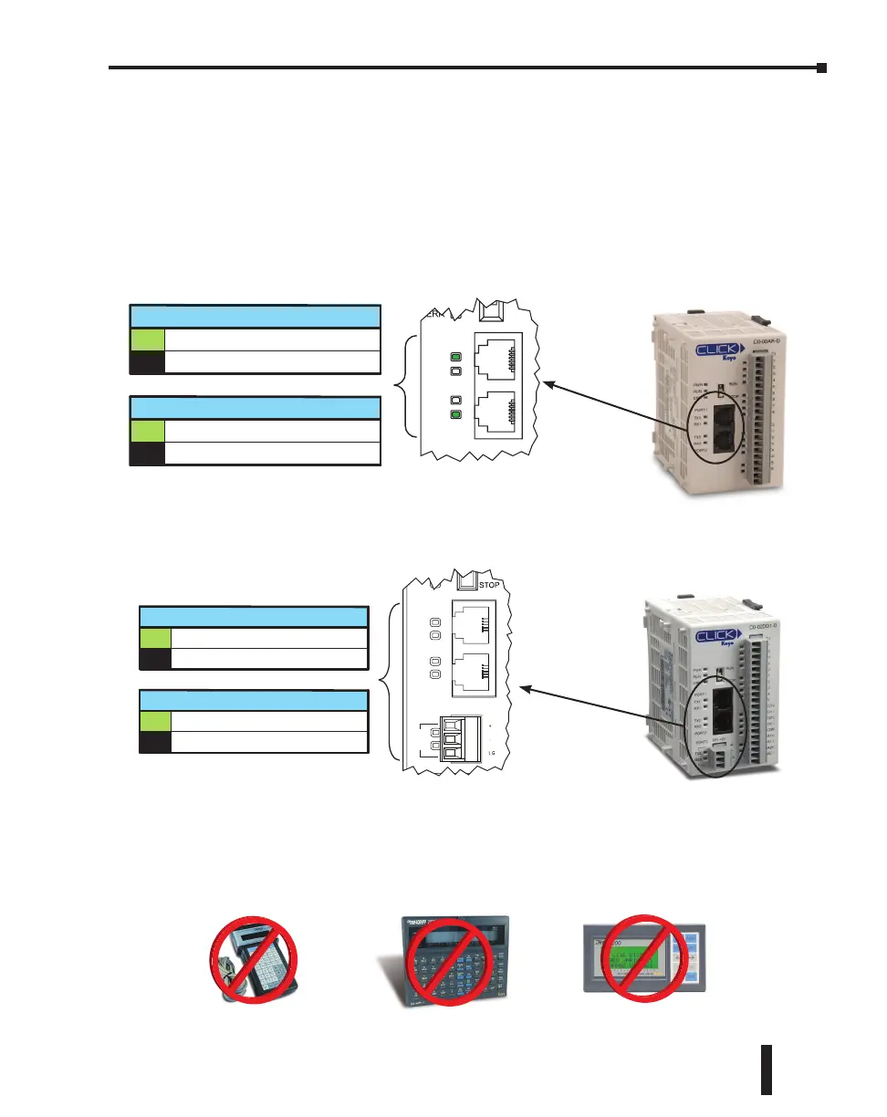
There are LED status indicators located to the left of each communication port to indicate port
activity or communications.
Port 1 & 2 LED
Status Indicators
STOP
PORT1
PORT2
TX1
TX2
RX1
RX2
RX1 and RX2 (Green)
On The Comm Port is receiving data.
The Comm Port is not receiving data.Off
TX1 and TX2 (Green)
On The Comm Port is sending data.
The Comm Port is not sending data.Off
Basic PLC
RS-485
PORT3
PORT2
PORT1
RUN
ERR
TX2
RX2
TX1
RX1
TX3
RX3
Status Indicators
RX1, RX2 and RX3 (Green)
On The Comm Port is receiving data.
The Comm Port is not receiving data.Off
TX1, TX2 and TX3 (Green)
On The Comm Port is sending data.
The Comm Port is not sending data.Off
Standard and Analog PLCs
DirectLogic Devices That Do Not Work With CLICK PLCs
The CLICK PLC does not support K-sequence protocol, so the following DirectLogic devices
do not work with the CLICK PLC:
D2-HPP
DV-1000
D4-HPP-1
CLICK PLC Hardware User Manual, 6th Edition, Rev. F – C0-USER-M
4–5
Chapter 4: PLC Communications

 Loading...