Powering I/O Circuits
In most applications, it will be necessary to power the input devices from one power source,
and to power output loads from another source. Loads often require high-energy AC power,
while input sensors use low-energy DC. If a machine operator is likely to come in close
proximity to input wiring, then for safety reasons, high-energy output circuits would be
isolated.
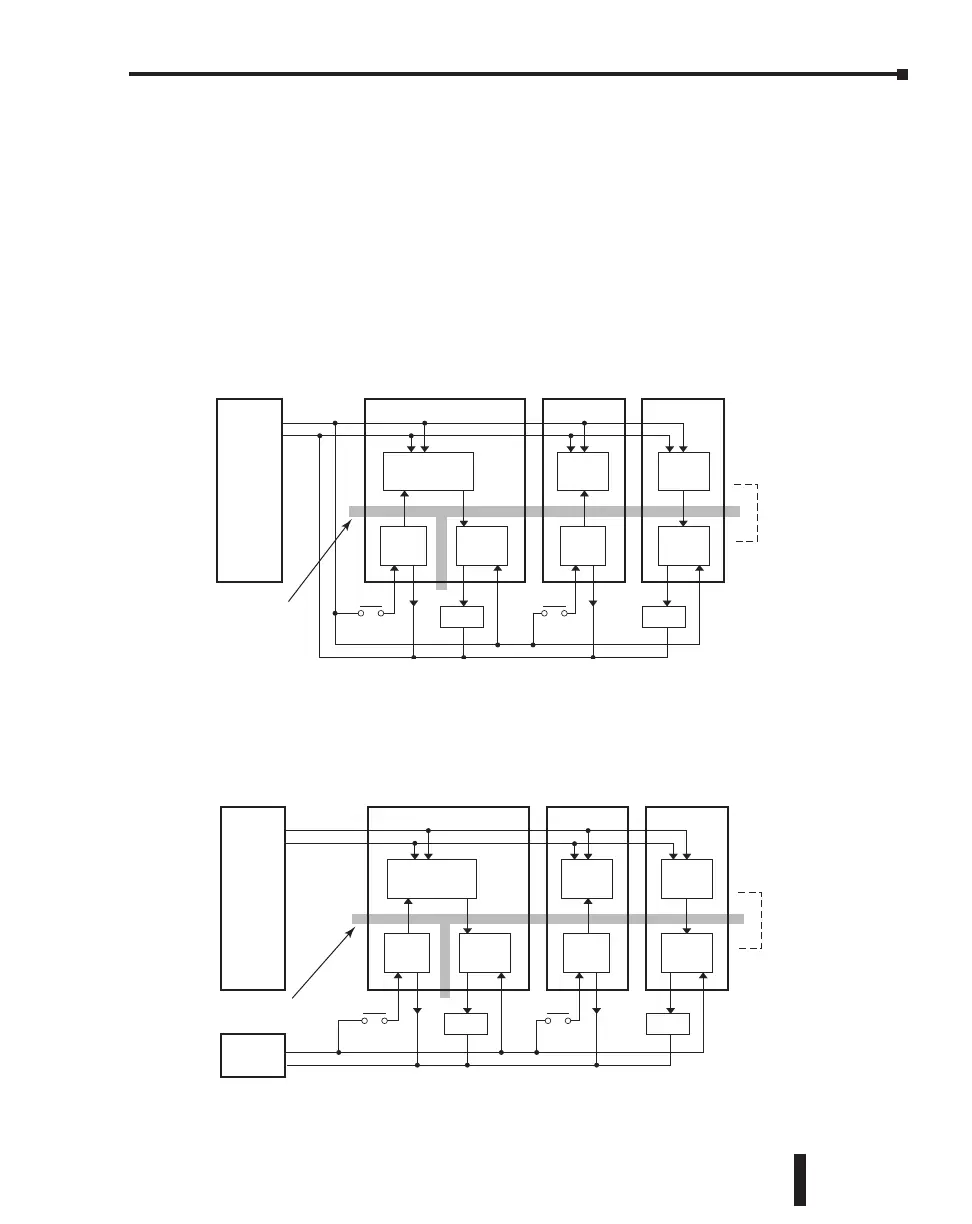
For the DC input/output circuits, you can use the same power source as the PLC module
(and I/O modules). However, you lose the isolation between the logic circuits and the input/
output circuits. For AC input/output circuits, you don’t need to worry about sharing the
24VDC.
24VDC
Output ModuleInput Module
Logic Circuit
Input
Circuit
Output
Circuit
Input
Circuit
Output
Circuit
Logic
Circuit
Logic
Circuit
0VDC
Isolation Boundary
LoadLoad
Lose
Isolation
To keep the isolation between the logic circuits and the input/output circuits, we recommend
using another power supply for the DC input and output circuits.
PLC Unit
24VDC
Output ModuleInput Module
Logic Circuit
Input
Circuit
Output
Circuit
Input
Circuit
Output
Circuit
Logic
Circuit
Logic
Circuit
0VDC
Isolation Boundary
LoadLoad
Keep
Isolation
Power
Supply
24VDC
CLICK PLC Hardware User Manual, 5th Edition, Rev. F – C0-USER-M
3–27
Chapter 3: Installation and Wiring

 Loading...