PLC Maintenance
Although the CLICK PLC requires very little maintenance, setting up a routine maintenance
schedule will ensure the longevity of the PLC in your application. We suggest checking the
following items as part of a quarterly or bi-annual preventative maintenance schedule.
Check LED Indicators
Check the PWR and ERR LED indicators on the PLC and I/O modules. If the PWR LED
indicator is off or flickering, or if the ERR indicator is on or flickering, refer to Chapter 6:
Troubleshooting for more information.
Project Backup
Saving a copy of the project file during routine maintenance ensures that you will have a
fairly up-to-date backup copy of the PLC program. Although the CLICK PLC programming
software can upload the complete project from the PLC anytime the PLC is operable, it is wise
to maintain a project backup in case the PLC becomes inoperable and has to be replaced. The
backup file of the project can then be downloaded into the new PLC.
Check Operating Environment
Make sure that the CLICK PLC is operating within the proper temperature range
(0–55°C; 32–131°F).
Make sure that the CLICK PLC is operating within the proper humidity range
(30–95% RH, non-condensing).
Make sure that the CLICK PLC operating environment is free of corrosive gases.
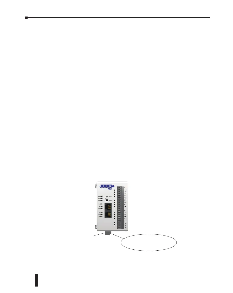
Check Operating Voltage
Check the input voltage that is powering the CLICK PLC to make sure that the voltage is
within the appropriate range (20–28 VDC).
Check the input voltage for the I/O module terminal blocks. Refer to Chapter 2: Specifications
for the voltage specifications of the various I/O modules.
C0-00DD1-D
24VDC Power Connector
Check the input voltage here,
at the power input terminal.
CLICK PLC Hardware User Manual, 6th Edition, Rev. F – C0-USER-M
5–2
Chapter 5: Maintenance

 Loading...