Analog PLC Unit Specifications
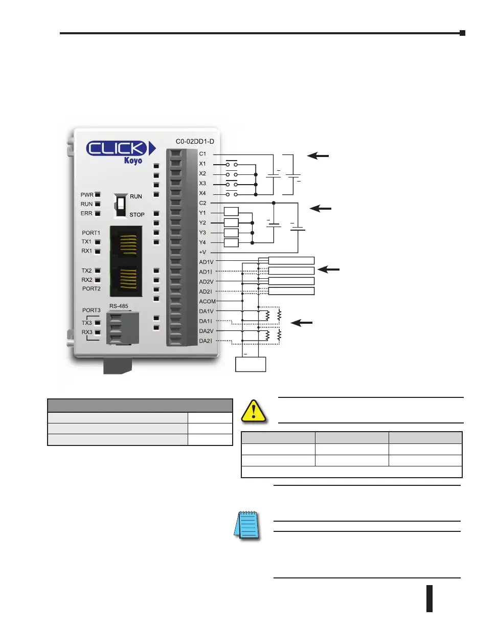
C0-02DD1-D – 4 DC Input/4 Sinking DC Output; 2 Analog In/2 Analog Out
Micro PLC
C0-02DD1-D
C1
X1
X2
X3
X4
C2
Y1
Y2
Y3
Y4
+V
AD1V
AD1I
AD2V
AD2I
ACOM
DA1V
DA1I
DA2V
DA2I
RS-485
PORT3
PORT2
PORT1
PWR
RUN
ERR
TX2
RX2
TX1
RX1
TX3
RX3
+
+
24VDC
5 - 27
VDC
+
+
+
L
24
VDC
L
L
L
Transmitter 0-5V
Transmitter 4-20mA
Transmitter 0-5V
Transmitter 4-20mA
Transmitter
P/S
Wiring Diagram
See Discrete I/O
Specifications - Inputs
(X1 through X4)
See Discrete I/O
Specifications - Outputs
(Y1 through Y4)
See Analog I/O Specifications -
Voltage & Current Input
(AD1V through AD2I)
See Analog Specifications -
Voltage & Current Output (DA1V
through DA2I)
NOTE: Please refer to the Analog I/O Configuration
section in Chapter 3 for information on using the
analog I/O.
NOTE: There are no ZIPLink pre-wired PLC
connection cables and modules for the Analog PLCs
(cannot mix discrete I/O and analog I/O signals in a
ZIPLink cable).
WARNING: You must use proper software and
firmware for this PLC unit.
Serial Number Software Firmware
Before 171208001 V1.12 or later V1.10 or later
171208001 or later V2.10 or later V2.10 or later
You can find the serial number on the bottom of the product label.
General Specifications
Current Consumption at 24VDC
140mA
Terminal Block Replacement Part No.
C0-16TB
Weight
5.3 oz (150g)
CLICK PLC Hardware User Manual, 6th Edition, Rev. G – C0-USER-M
2–51
Chapter 2: Specifications

 Loading...