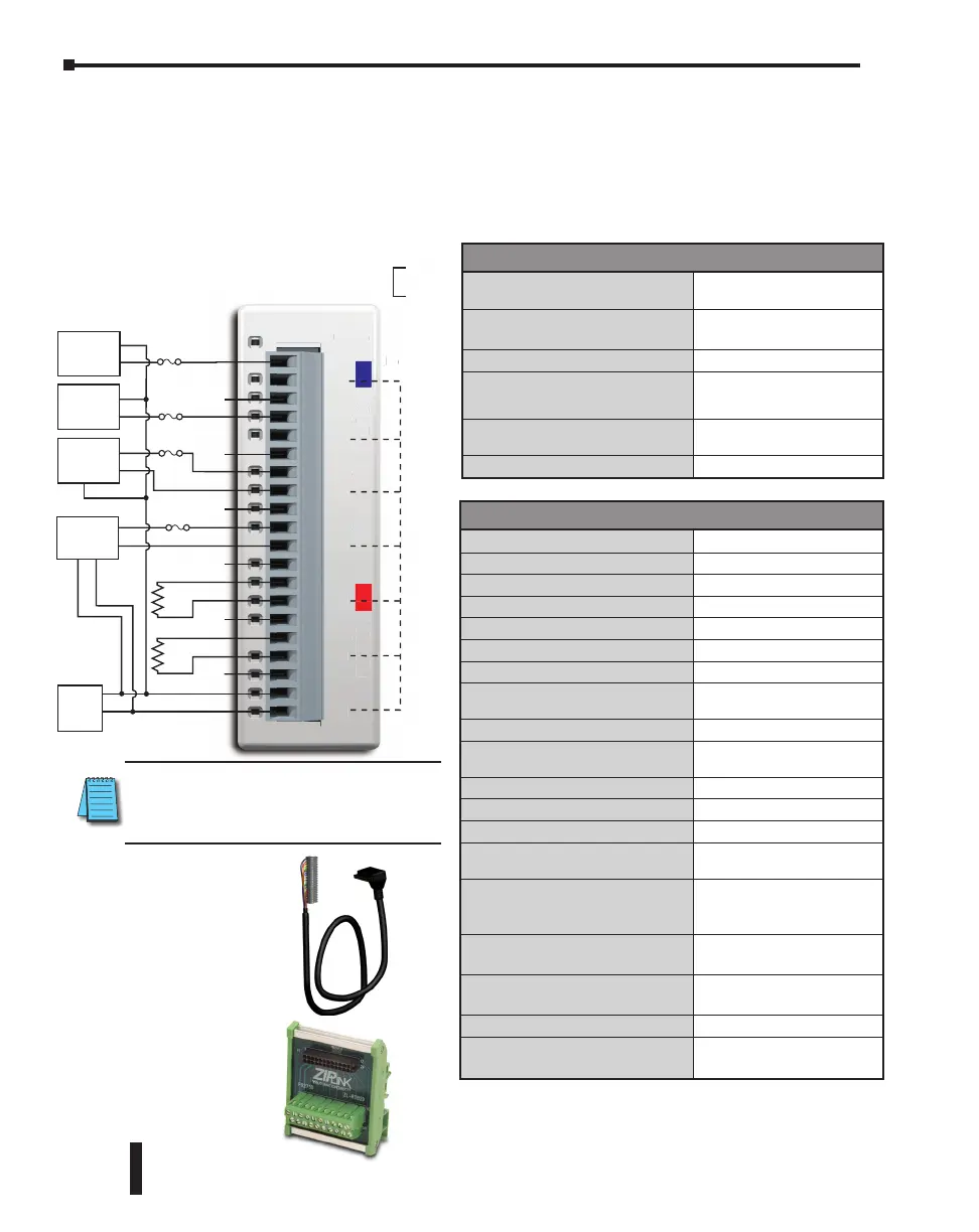
General Specifications
Field to Logic Side Isolation
1800VAC for 1 sec.
External 24VDC Power
Required
75mA
Bus Power Required (24VDC)
25mA
Recommended Fuse (External)
AutomationDirect p/n S500-
32-R
(0.032 A fuse)
Terminal Block Replacement
AutomationDirect p/n
C0-16TB
Weight
3.1 oz (86g)
Input Specifications
Inputs per Module
4
Input Range
0-20 mA (sink)
Resolution
13-bit, 2.44 uA per count
Input Type
Single ended (one common)
Maximum Continuous Overload
±44 mA
Input Impedance
124q, 0.5 W current input
Filter Characteristics
Low pass, -3 dB at 400 Hz
PLC Data Format
13-bit unsigned Integer, range
is 0-8191
Sample Duration Time
5 ms
All Channel Update Rate
20 ms (input plus output
maximum time)
Open Circuit Detection Time
Zero reading within 20 ms
Conversion Method
Successive approximation
Accuracy vs. Temperature
±75 PPM/°C maximum
Maximum Inaccuracy
0.5% of range (including
temperature changes)
Linearity Error (End to End)
±3 count maximum,
monotonic with no missing
codes
Input Stability and
Repeatability
±2 count maximum
Full Scale Calibration Error
(Including Offset)
±8 count maximum
Offset Calibration Error
±8 count maximum
Maximum Crosstalk at DC,
50/60 Hz
±2 count maximum
C0-4AD2DA-1 – 4-Channel Analog Current Input and 2-Channel Analog
Current Output Module
4-channel analog current sinking input (13-bit resolution) and 2-channel analog current
sourcing output (12-bit resolution) module, range: 0–20 mA (inputs), 4–20 mA (outputs).
External 24VDC power required, removable terminal block included.
C0-4AD2DA-1
0-20mA In
4-20mA Out
OUTPUT
INPUT
CH1
0V
CH2
0V
CH3
0V
CH4
0V
CH1
0V
CH2
0V
24V
0V
All ‘0V’
terminals are
connected
internally.
C0-4AD2DA-1
-
mA I
-2
mA
CH1
H2
H3
CH4
H1
H2
All
o
nt
Load
Load
N.C.
N.C.
N.C.
N.C.
N.C.
N.C.
N.C. =
Not Connected
+
–
2-wire
4-20mA
Transmitter
+
+
–
–
+
–
3-wire
4-20mA
Transmitter
*
*
*
*
+
+
–
24VDC
Module
Supply
*0.032A fast-acting fuse
(ADC p/n S500-32-R)
is recommended.
CHn
0V
Connect the unused input
channel to 0V terminal.
+
–
2-wire
4-20mA
Transmitter
4-wire
4-20mA
Transmitter
Wiring Diagram
ZIPLink Pre-Wired PLC
Connection Cables and
Modules for CLICK PLC
ZL-RTB20 20-pin
feed-through
connector module
20-pin connector cable
ZL-C0-CBL20 (0.5 m length)
ZL-C0-CBL20-1 (1.0 m length)
ZL-C0-CBL20-2 (2.0 m length)
NOTE: When using this module you must
also use CLICK programming software and
PLC firmware version V1.40 or later.
CLICK PLC Hardware User Manual, 6th Edition, Rev. G – C0-USER-M
2–144
Chapter 2: Specifications

 Loading...