Step 5: Apply Power
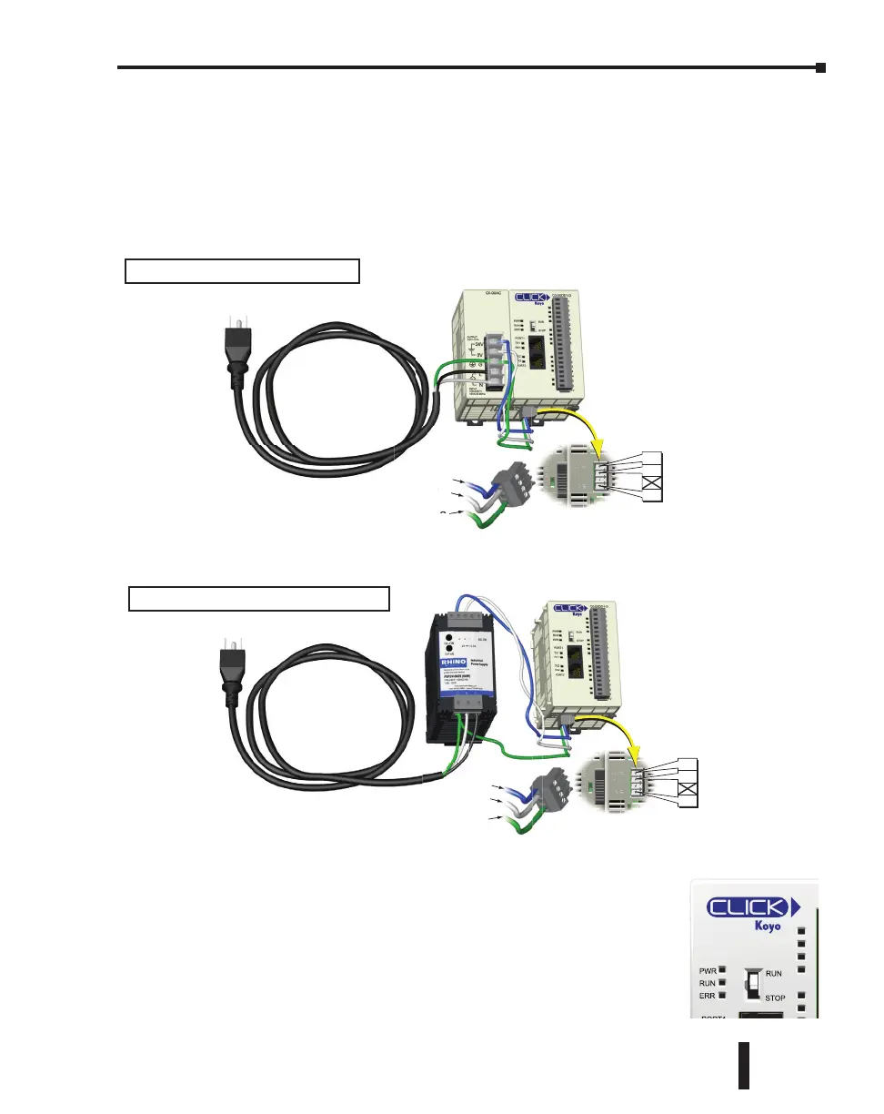
The CLICK PLC system works with 24 VDC power. There is a small terminal block on the
bottom of the CLICK PLC unit. Wire the 24 VDC output from a CLICK power supply, or
a properly sized and rated 24 VDC power supply such as AutomationDirect’s RHINO series,
to the bottom terminal block (See Chapter 2: Specifications for power supply specifications.)
EITHER
OR
Once you wire and power up the power supply, confirm the PWR
indicator (Green LED) on the CLICK PLC unit is on.
If the PWR indicator is not on, check the voltage on the terminal block
with a voltage meter. If you measure 24 VDC on the terminal block, the
CLICK PLC unit may be defective. Please try another one or contact us
for a replacement.
24V
0V
G
24V
0V
G
V
24V
0V
G
24V
0V
G
Using an alternate 24 VDC Power Supply.
Using a CLICK 24 VDC Power Supply.
Power Terminal Block
Power Terminal Block
C0-00DD1-D
TX1 & RX1
Indicators
CLICK PLC Hardware User Manual, 6th Edition, Rev. G – C0-USER-M
1–15
Chapter 1: Getting Started

 Loading...