System Wiring Strategies
The CLICK PLC system is very flexible and will work in many different wiring configurations.
By studying this section before actual installation, you can find the best wiring strategy for your
application. This will help to lower system cost and wiring errors, and avoid safety problems.
PLC Isolation Boundaries
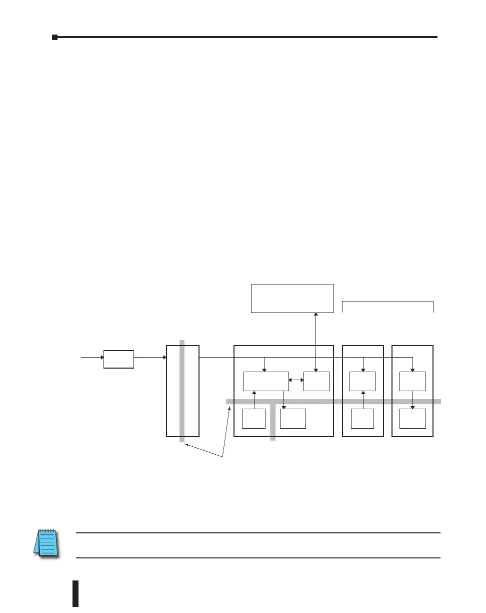
PLC circuitry is divided into three main regions separated by isolation boundaries, shown
in the drawing below. Electrical isolation provides safety, so that a fault in one area does
not damage an adjacent area. A powerline filter will provide isolation between the power
source and the power supply. The transformer in the power supply provides magnetic isolation
between the primary and secondary sides. Optical isolators provide optical isolation in Input
and Output circuits. These methods isolate logic circuitry from the field side, where factory
machinery connects. The discrete inputs are isolated from the discrete outputs, because each is
isolated from the logic side. Isolation boundaries protect the devices such PC and HMI that are
connected to the communication ports, from power input faults or field wiring faults. When
wiring a PLC, it is extremely important to avoid making external connections that connect
logic side circuits to more than one circuit.
PLC Unit
Power Supply
Power
Input
24VDC
PC, HMI, or other
communication devices
Output ModuleInput Module
Isolation Boundary
Logic Circuit
Com
Ports
Input
Circuit
Output
Circuit
Input
Circuit
Output
Circuit
Logic
Circuit
Logic
Circuit
Filter
Maximum 8 I/O Modules
NOTE: If you do not use one of the CLICK PLC power supplies C0-00AC and C0-01AC to provide 24VDC
to the PLC module (and I/O modules), be sure the power supply you use has isolation with a transformer.
CLICK PLC Hardware User Manual, 5th Edition, Rev. F – C0-USER-M
3–26
Chapter 3: Installation and Wiring

 Loading...