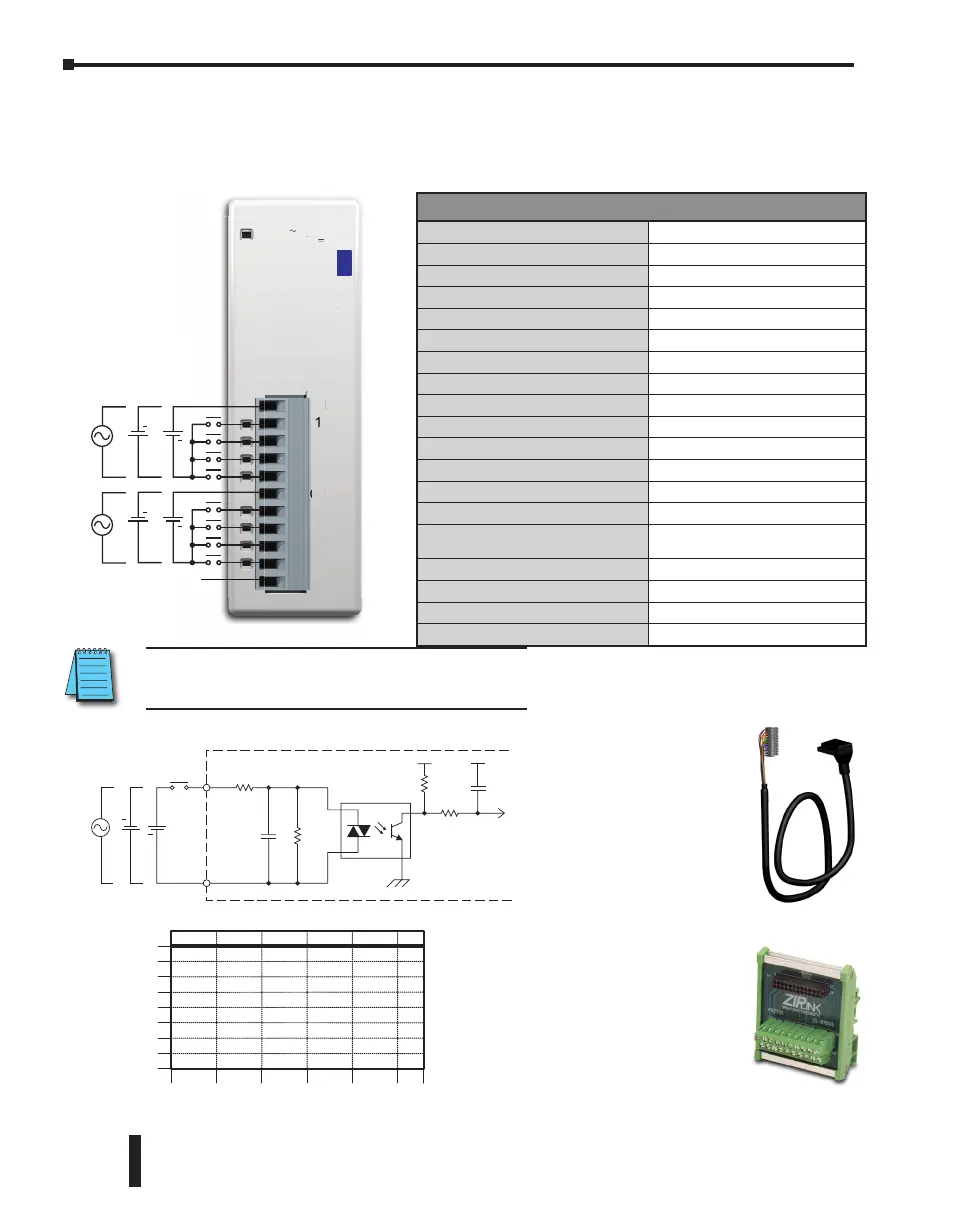
Input Specifications
Inputs per Module
8 (Sink/Source)
Operating Voltage Range
24 VAC/VDC
Input Voltage Range
20.4–27.6 VAC/VDC
Peak Voltage
27.6 VAC/VDC
AC Frequency
47–63 Hz
Input Current
Typ 3.4 mA @ 24 VAC/VDC
Maximum Input Current
5.0 mA @ 27.6 VAC/VDC
Input Impedance
6.8 Kq @ 24 VAC/VDC
ON Voltage Level
> 18.0 VAC/VDC
OFF Voltage Level
< 4.0 VAC/VDC
Minimum ON Current
2.5 mA
Maximum OFF Current
0.5 mA
OFF to ON Response
5–40 ms
ON to OFF Response
10–50 ms
Status Indicators
Logic Side (8 points, green LED)
Power Indicator (green LED)
Commons
2 (4 points/common) Isolated
Bus Power Required (24VDC)
Max. 30mA (All Inputs On)
Terminal Block Replacement
AutomationDirect p/n C0-8TB
Weight
2.9 oz (82g)
C0-08NE3 – 8-Point Sink/Source AC/DC Input Module
8-point 24VAC / 24VDC current sinking or sourcing input module, 2 commons, 4 points per
common, removable terminal block included.
0
Surrounding Temperature (°C/°F)
32
10
50
20
68
30
85
40
104
50
122
55 °C
131 °F
2
4
6
8
Points
Input Module Temperature Derating Chart
0
INPUT
COM
Internal Module Circuitry
Optical Isolator
24 VDC
+
+
24VAC
C2
7
3
2
5
4
8
6
1
C1
C0-08NE3
24V 3.4mA/pt.
24V
〜
50/60Hz 3.4mA/pt.
PWR
INPUT
2
1
-
.4mA/
t.
50
60Hz 3.4mA
pt.
N.C.
N.C. = Not Connected
24 VDC
+
+
24 VDC
+
24 VAC
24 VAC
+
ZIPLink Pre-Wired PLC Connection
Cables and Modules for CLICK PLC
11-pin connector cable
ZL-C0-CBL11 (0.5 m length)
ZL-C0-CBL11-1 (1.0 m length)
ZL-C0-CBL11-2 (2.0 m length)
Wiring Diagram
ZL-RTB20
20-pin feed-through
connector module
NOTE: When using this module you must also use
CLICK programming software version V1.20 or later.
CLICK PLC Hardware User Manual, 6th Edition, Rev. G – C0-USER-M
2–118
Chapter 2: Specifications

 Loading...