LED Indicators
The CLICK PLC performs many pre-defined diagnostic routines with every PLC scan, using
onboard diagnostics that can detect various errors or failures in the PLC. LEDs on the face of
the PLC will indicate for specific errors.
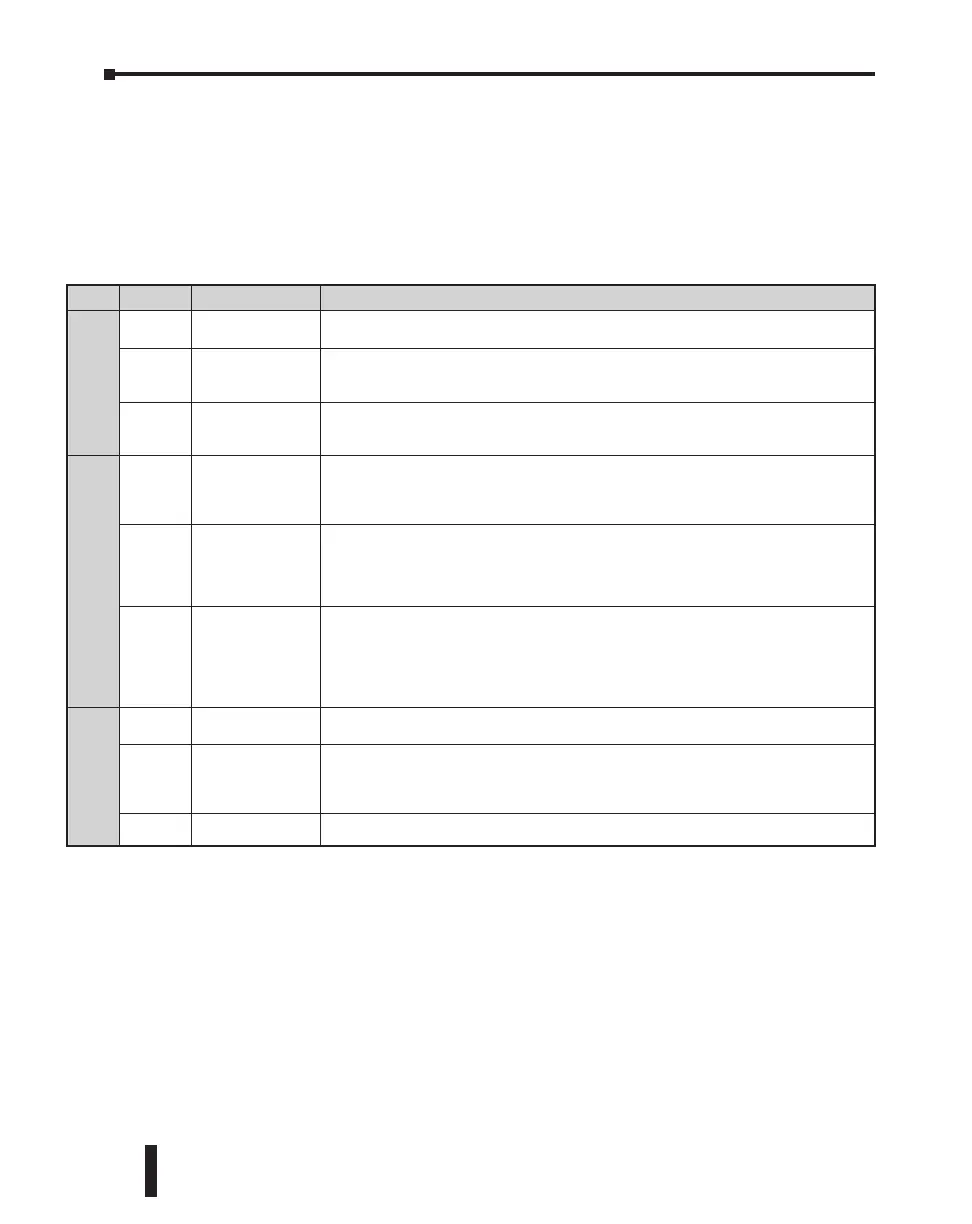
The 3 LEDs located next to the RUN/STOP switch power, (PWR, RUN and ERR) indicate
the status of the PLC unit. The remainder of the LED indicators are discussed in later sections
of this chapter:
• TX1/RX1/TX2/RX2/TX3/RX3 & LINK/ACT – Chapter 2
• • LED indicators for I/O – Chapter 2
LED Status Meaning Necessary action
PWR
On
The PLC is powered
correctly.
No action is necessary.
Blinking
The PLC input
power is not
sufficient.
Check the voltage on the terminal located on the bottom of the PLC. The input voltage
should be 20-28 VDC. Also check the power input wiring & terminal connections. The
power supply may need to be replaced.
Off
There is no power
to the PLC.
Check the voltage on the terminal located on the bottom of the PLC. The input voltage
should be 20-28 VDC. Also check the power input wiring & terminal connections. The
power supply may need to be replaced.
RUN
On
The PLC is in RUN
mode.
If the toggle switch next to the LED indicators is in RUN position, no action is necessary. If
the toggle switch is in STOP position, cycle power the PLC. If the PLC unit starts up in Run
mode, it means that the PLC unit does not recognize the toggle switch position correctly,
and the PLC unit must be replaced.
Blinking
The PLC is
initializing the
C0-04RTD or
C0-04THM.
When a C0-04RTD or C0-04THM is installed in the CLICK PLC system, the RUN LED blinks
for up to 11 seconds to indicate that the PLC unit is initializing the analog input module after
power-up. If the RUN LED keeps blinking after the initial 11 seconds, power cycle the CLICK
PLC system. If the symptom remains, replace the PLC unit and/or the analog input module.
Off
The PLC is in STOP
mode.
If the toggle switch next to the LED indicators is in STOP position, no action is necessary.
If the switch is in RUN position and you want to put the PLC unit in Run mode, toggle
the switch to STOP position and then back to RUN position. If the RUN LED stays off,
connect the CLICK programming software to read the error information. See the “Error
Codes” section at the end of this chapter for error message instructions.
ERR
On There is an error.
Connect the CLICK programming software to check the error. See the “Error Codes”
section at the end of this chapter for error message instructions.
Blinking There is a warning.
Warnings do not prevent the PLC unit from running. However, you should check what
warnings are active. Connect the CLICK programming software to read the warning
information. See the “Error Codes” section at the end of this chapter for error message
instructions.
Off There is no error. No action is necessary.
Errors (ERR LED on)
Errors which may cause the system to function improperly, perhaps causing a safety problem. The PLC will automatically
switch from RUN Mode to STOP Mode. (In STOP Mode all outputs are turned off.) If the PLC is already in STOP Mode
when an error is detected, the PLC will not allow a transition to RUN Mode until the error has been corrected.
Examples of errors:
• I/O module error
• System configuration error
• Memory check error
• Project file error
Warnings (ERR LED blinking)
Warnings that require attention, but do not cause improper operation. They do not cause or prevent any PLC mode
transitions. The application program can use system control bits to detect warnings, and even take the system to an orderly
shutdown or switch the PLC to STOP Mode if desired. Examples of warnings:
• Lost SRAM data
• Battery low voltage
CLICK PLC Hardware User Manual, 6th Edition, Rev. F – C0-USER-M
6–4
Chapter 6: Troubleshooting

 Loading...