Analog I/O Configuration
Built-in Analog I/O are available in the CLICK models listed below. (Expansion Analog I/O
modules are shown on following page.)
Terminal Block Wiring - Analog PLC Units
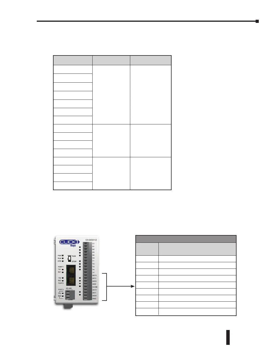
The (non-Ethernet) Analog PLC units have two built-in analog inputs and two built-in analog
outputs. You can select analog voltage or analog current for each analog I/O separately. As
shown below, you must use the proper terminal when using analog voltage or analog current.
Analog Terminals
Terminal
Name
Terminal Description
AD1V Analog voltage input
AD1I Analog current input
AD2V Analog voltage input
AD2I Analog current input
ACOM Common for all analog inputs and outputs
DA1V Analog voltage output
DA1I Analog current output
DA2V Analog voltage output
DA2I Analog current output
C0-02DD1-D
C1
X1
X2
X3
X4
C2
Y1
Y2
Y3
Y4
+V
AD1V
AD1I
AD2V
AD2I
ACOM
DA1V
DA1I
DA2V
DA2I
RS-485
PORT3
PORT2
PORT1
PWR
RUN
ERR
TX2
RX2
TX1
RX1
TX3
RX3
Analog PLC Units Inputs Outputs
C0-02DD1-D
2 - Current/ Voltage,
Selectable
2 - Current/ Voltage,
Selectable
C0-02DD2-D
C0-02DR-D
C0-12DD1E-D
C0-12DD2E-D
C0-12DRE-D
C0-12ARE-D
C0-12DD1E-1-D
4 - Current only 2 - Current only
C0-12DD2E-1-D
C0-12DRE-1-D
C0-12ARE-1-D
C0-12DD1E-2-D
4 - Voltage only 2 - Voltage only
C0-12DD2E-2-D
C0-12DRE-2-D
C0-12ARE-2-D
CLICK PLC Hardware User Manual, 5th Edition, Rev. F – C0-USER-M
3–37
Chapter 3: Installation and Wiring

 Loading...