C-3: Com Port 2 Setup (Modbus RTU)
Before you set up the communication ports you must connect the PC with the CLICK
programming software to the CLICK PLC Port 1 using a D2-DSCBL or EA-MG-PGM-CBL
programming cable. Refer to Chapter 1: Getting Started for step-by-step instructions for this
connection. Once the PC and programming software are online with the CLICK PLC, click
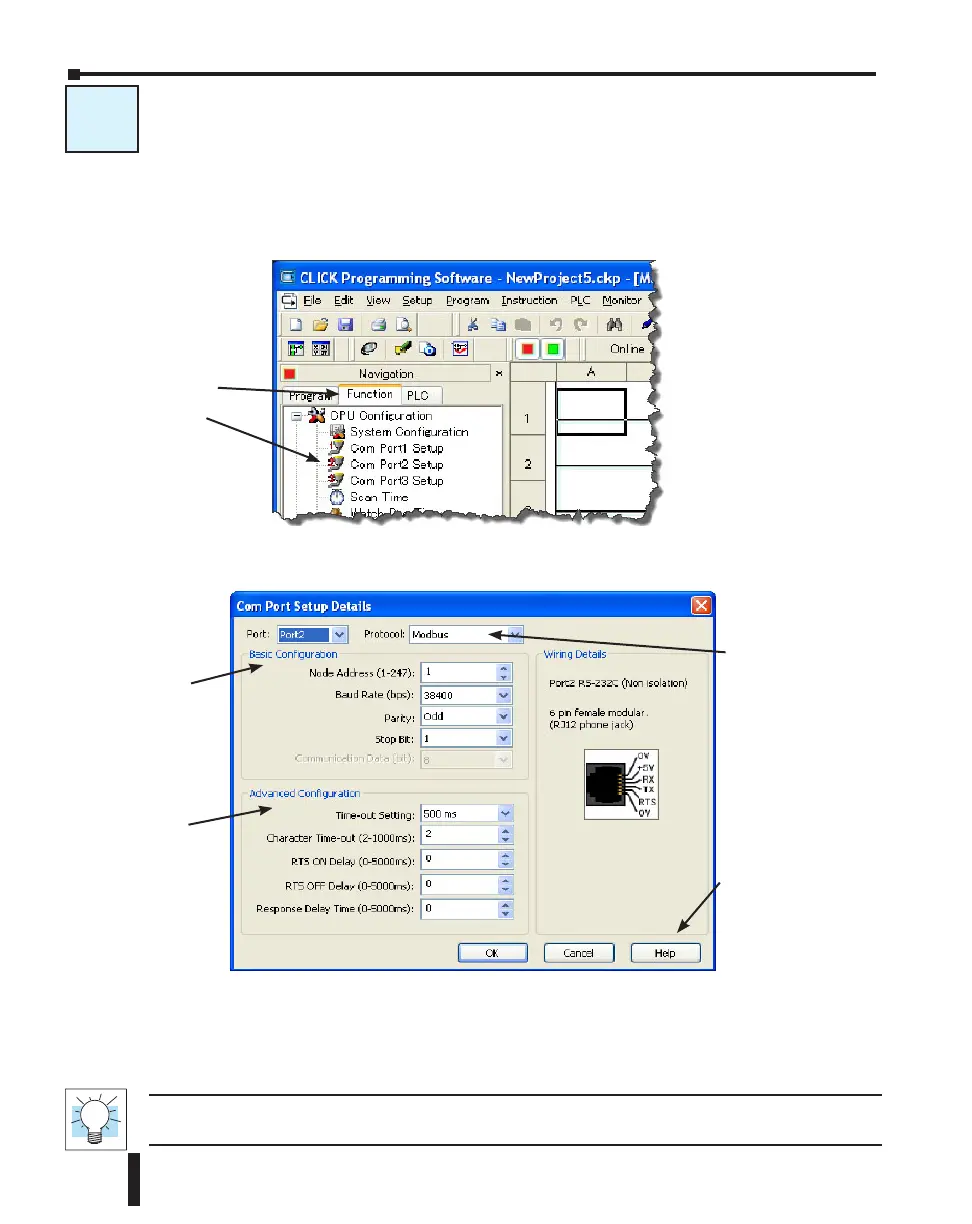
the Function tab located in the Navigation window and double click Com Port2 Setup as
shown below.
The Com Port Setup Details dialog box will come into view as shown below.
Find the Basic Configuration section in the dialog box and set up the parameters to match other
devices in the same network. The dialog box also has a section named Advanced Configuration.
You may need to make adjustments to these parameters to overcome communication errors
which may occur.
TIP : The communication port settings are saved in the project file. The project must be transferred to the
CLICK PLC in order for any port setting changes to take effect.
Set up the
parameters to match
other devices in the
same network.
Make any
adjustments here
to eliminate Com
errors.
Select Modbus.
Click the Help button
for Com Port Setup
Details online help.
C-3
Select the Function tab,
then double click Com
Port2 Setup.
CLICK PLC Hardware User Manual, 6th Edition, Rev. F – C0-USER-M
4–22
Chapter 4: PLC Communications