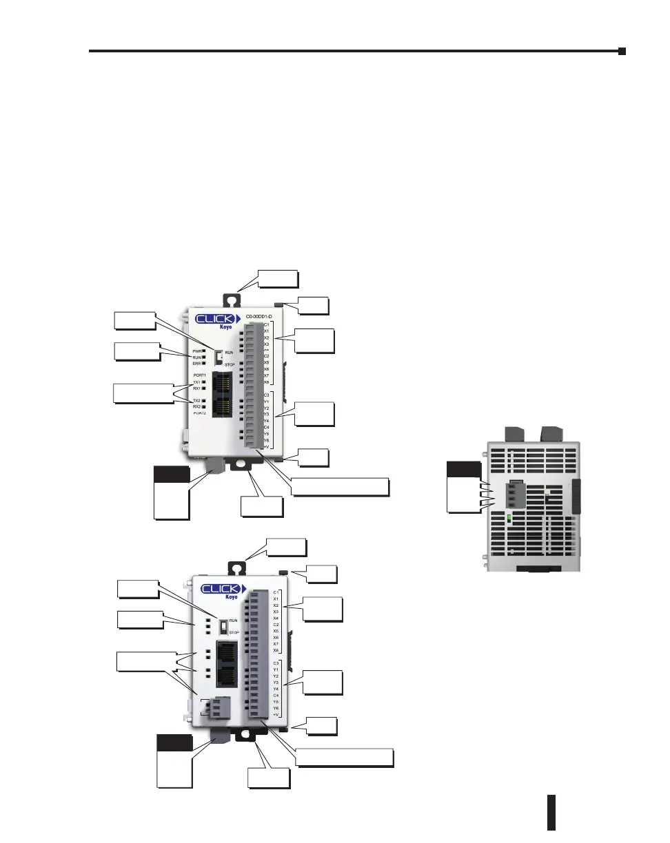
LED Status
Indicators
PLC Mode
Switch
8 Discrete
Input
Points
6 Discrete
Output
Points
Communication
Ports
Sliding
Latch
Sliding
Latch
Mounting
Tab
Power
Terminal
24V
0V
N.C.
G
Removeable Screw Type
Terminal Block
Mounting
Tab
Introduction to the CLICK PLC Mechanical Design
CLICK PLC Units
All CLICK PLCs are similar in appearance. Please see the diagrams below to familiarize
yourself with the PLC features. The main components located on the front of the PLC are
a removable 20-pin I/O connector, Run/Stop switch, communications ports and LED status
indicators. A removable 4-pin 24VDC input power connector is located on the bottom of
the PLC. The I/O module extension port is located on the right side of the PLC case. See
Mounting Guidelines in this chapter for module dimensions and Chapter 2 for CLICK PLC
specifications.
Component Locations on Basic and Standard PLC Units
Basic PLC
C0-01DD1-D
RS-485
PORT3
PORT2
PORT1
PWR
RUN
ERR
TX2
RX2
TX1
RX1
TX3
RX3
LED Status
Indicators
PLC Mode
Switch
8 Discrete
Input
Points
6 Discrete
Output
Points
Communication
Ports
Sliding
Latch
Sliding
Latch
Mounting
Tab
Power
Terminal
24V
0V
N.C.
G
Removeable Screw Type
Terminal Block
Mounting
Tab
Standard PLC
Power
Terminal
24V
0V
N.C.
G
24V
0V
G
Bottom v iew same for all PLC’s
CLICK PLC Hardware User Manual, 5th Edition, Rev. F – C0-USER-M
3–5
Chapter 3: Installation and Wiring

 Loading...