WARNING: For some modules, field device power may still be present on the terminal block even
though the PLC system is turned off. To minimize the risk of electrical shock and equipment damage,
check all field device power before you remove the connector.
Wiring I/O Modules
There are three sizes of I/O module terminal blocks used for field wiring connections (11pt,
13pt & 20pt). They can be removed from the module for wiring convenience. There are no
clips or screws retaining the terminal block. Firmly grip the block and pull it away from the
PLC or I/O module. The connector terminal points have recessed screws to help minimize
the risk of someone accidentally touching active wiring. Make sure the terminal blocks are
properly seated against the module when replacing them and wiring is properly constrained.
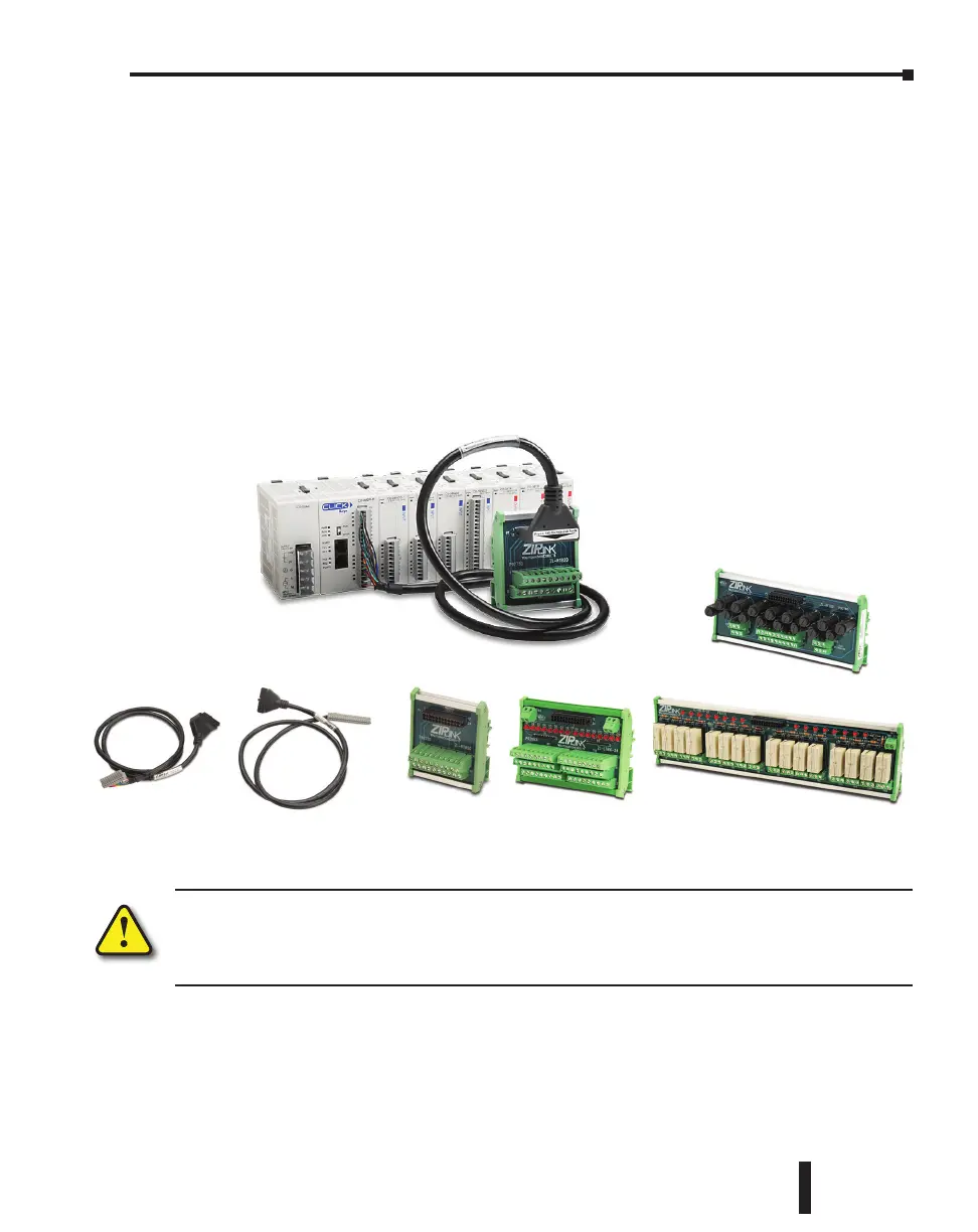
For your convenience we also have DINnectors, DIN-rail mounted terminal blocks. Refer to
our website or catalog for a complete listing of all available products. We strongly recommend
using our ZIPLinks connections systems. See the following pages for ZIPLink compatibility
and special pre-assembled cables, with the I/O connectors installed and wired.
ZIPLinks Cables with Connectors
ZIPLinks Modules
ZIPLinks Connection Systems
CLICK PLC Hardware User Manual, 5th Edition, Rev. F – C0-USER-M
3–21
Chapter 3: Installation and Wiring

 Loading...