Output Specifications
Outputs per Module
4
Output Range
0–10 V
Resolution
12-bit, 2.44 mV per count
Output Type
Voltage sourcing at 10mA max.
(One common)
Output Value in Program Mode
Determined by PLC
Output Value in Fault Mode
0 V
Output Impedance
0.2 q typical
Load Impedance
>1000q
Maximum Capacitive Load
0.01 uF maximum
Allowed Load Type
Grounded
Maximum Inaccuracy
0.5% of range
Max. Full Scale Calibration
Error (Not including Offset)
±0.2% of range maximum
voltage
Max. Offset Calibration Error
±0.2% of range maximum
Accuracy vs. Temperature
±75 PPM/°C maximum full scale
calibration change (±0.0025%
of range/°C)
Max. Crosstalk at DC, 50/60 Hz
-72 dB, 1 LSB
Linearity Error (End to End)
±4 LSB max., (±0.1% of full
scale); monotonic with no
missing codes
Output Stability and
Repeatability
±2% LSB after 10 minute
warmup period typical
Output Ripple
0.1% of full scale
Output Settling Time
0.3 ms maximum, 5 μs
minimum (full scale range)
All Channel Update Rate
10ms
Max. Continuous Overload
Outputs current limited to 40mA
typical; continuous overloads
on multiple outputs can damage
module.
Field to Logic Side Isolation
1800VAC applied for 1 second
(100% tested)
Type of Output Protection
0.1 μF transient suppressor
Output Signal at Power Up and
Power Down
0 V
External 24VDC Power
Required
85mA
Base Power Required (24VDC)
20mA
Terminal Block Replacement
AutomationDirect p/n C0-8TB
Weight
2.9 oz (82g)
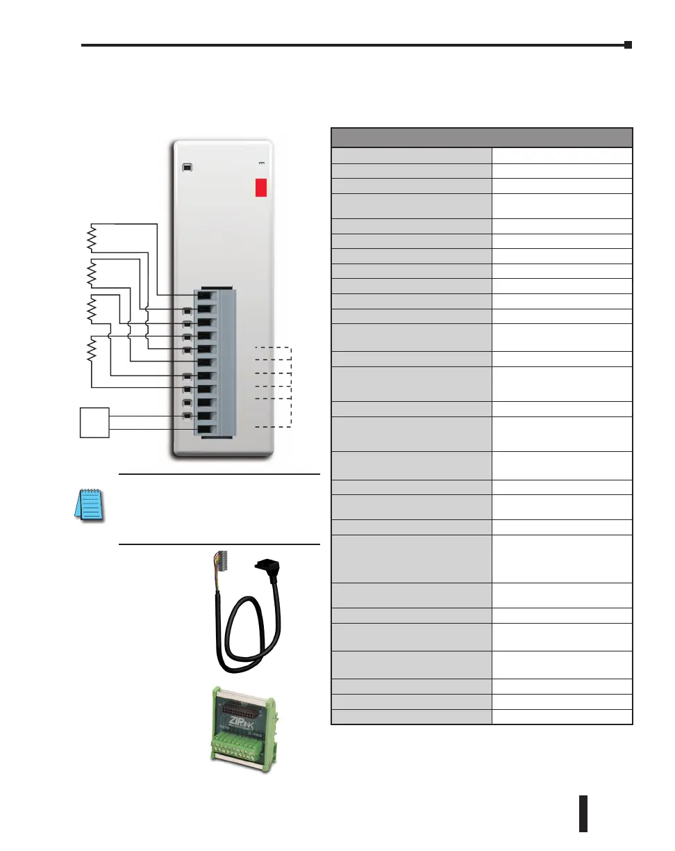
C0-04DA-2 – 4-Channel Analog Voltage Output Module
4-channel analog voltage output module, 12-bit resolution, range: 0–10 V. External 24VDC
power required, removable terminal block included.
CH1
CH2
CH3
CH4
0V
0V
0V
0V
0V
24V
0V
C0-04DA-2
0-10V
OUTPUT
+
–
24VDC
Power
Supply
Ch1
Load
Ch2
Load
Ch4
Load
Ch3
Load
All ‘0V’
connected
internally.
Wiring Diagram
ZIPLink Pre-Wired PLC
Connection Cables and
Modules for CLICK PLC
11-pin connector cable
ZL-C0-CBL11 (0.5 m length)
ZL-C0-CBL11-1 (1.0 m length)
ZL-C0-CBL11-2 (2.0 m length)
ZL-RTB20 20-pin
feed-through
connector module
NOTE: When using this module you
must also use CLICK programming
software and PLC firmware version
V1.40 or later.
CLICK PLC Hardware User Manual, 6th Edition, Rev. G – C0-USER-M
2–143
Chapter 2: Specifications

 Loading...