RS-485
+
_
LG
LNK/ACT
PORT1
PWR
RUN
ERR
RUN
STOP
PORT2
PORT3
RS-232
TX2
RX2
100MBIT
ETHER
NET
TX3
RX3
L
P
RT2
TX
-
T
R
NK
A
P
RT
R
ER
C0-12DD2E-D
C1
X1
X2
X3
X4
V1
Y1
Y2
Y3
Y4
CO
AD1V
AD1 I
AD2V
AD2 I
ACOM
DA1V
DA1 I
DA2V
DA2 I
+
+
24VDC
+
+
L
24
VDC
L
L
L
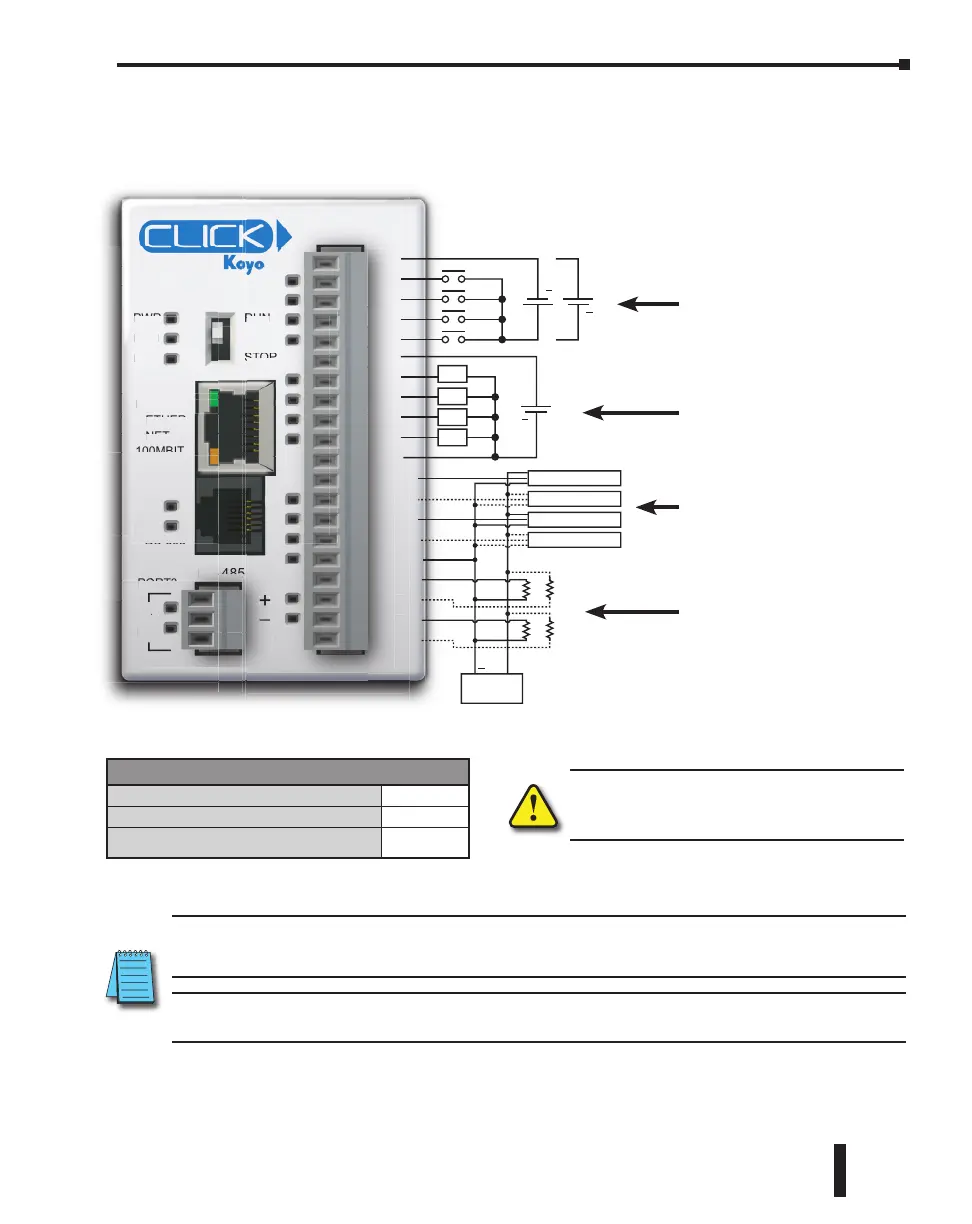
Transmitter 0-5V
Transmitter 4-20mA
Transmitter 0-5V
Transmitter 4-20mA
Transmitter
P/S
Wiring Diagram
NOTE: Please refer to the Analog I/O Configuration section in Chapter 3 for information on using the
analog I/O.
NOTE: There are no ZIPLink pre-wired PLC connection cables and modules for the Ethernet Analog PLCs
(cannot mix discrete I/O and analog I/O signals in a ZIPLink cable).
WARNING: When using an Ethernet Analog
PLC unit, you must use CLICK programming
software version V2.20 or later.
General Specifications
Current Consumption at 24VDC
140mA
Terminal Block Replacement Part No.
C0-16TB
Weight
5.08 oz
(144g)
C0-12DD2E-D – 4 DC Input (Sink/Source)/4 Sourcing DC Output;
2 Analog Voltage/Current Input
2 Analog Voltage/Current Output Micro PLC
See Discrete I/O Specifications
Outputs (Y1 – Y4)
See Analog I/O Specifications
Voltage & Current
Inputs (AD1V – AD2I)
See Analog I/O Specifications
Voltage & Current
Outputs (DA1V – DA2I)
See Discrete I/O Specifications
Inputs (X1 – X4) High-Speed
CLICK PLC Hardware User Manual, 6th Edition, Rev. G – C0-USER-M
2–79
Chapter 2: Specifications

 Loading...