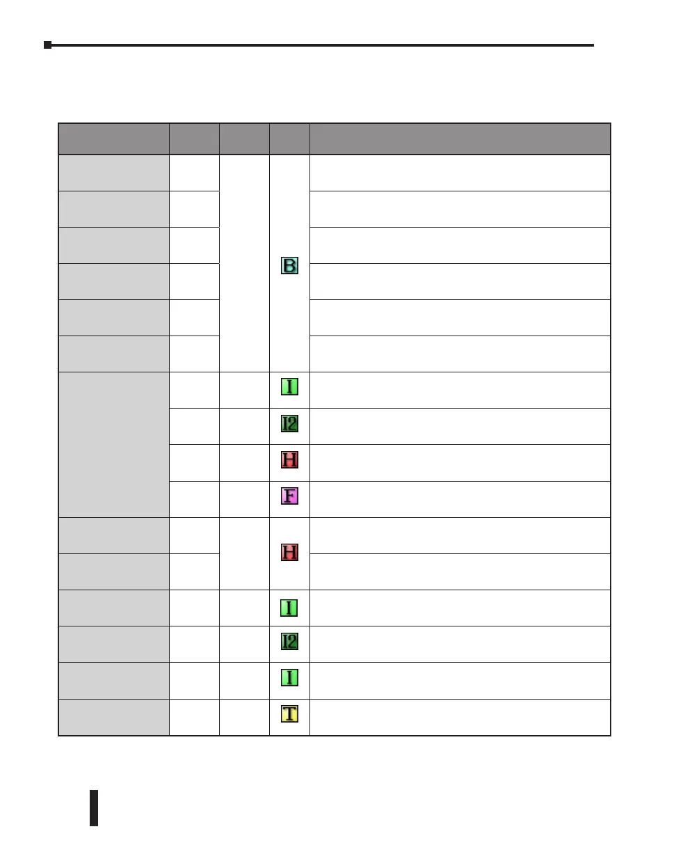
Memory Types
The following is the list of the memory types that the CLICK PLC system supports. See the
memory map later in this chapter.
Memory Type Symbol
Data
Type
S/W
Icon
Definition
Input Point
X
Bit
The Discrete Input points are represented by the “X” symbol.
Output Point
Y The Discrete Output points are represented by the “Y” symbol.
Control Relay
C
The Control Relay bits are represented by the “C” symbol. These
internal bits are typically used for ladder program control. They do
not represent any real world inputs or outputs.
Timer
T
The Timers are represented by the “T” symbol. The Timer status bit is
used to indicate when the Current Value of the timer equals its Preset
Value.
Counter
CT
The Counters are represented by the “CT” symbol. The Counter status
bit is used to indicate when the Current Value of the counter equals its
Preset Value.
System Control
Relay
SC
The internal System Control Relays, represented by the “SC” symbol,
are pre-defined bits which represent the status of specific system
functions.
Data Register
DS Integer
Single word integer data registers are represented by the “DS”
symbol.
DD Integer2
Double word integer data registers are represented by the “DD”
symbol.
DH HEX Single word Hex data registers are represented by the “DH” symbol.
DF
Floating
Point
Data Floating Point registers are IEEE format Real number values
represented by the “DF” symbol as 32-bit words.
Input Register
XD
HEX
The Input Registers, represented by the “XD” symbol, contain groups
of Discrete Input points in a 16-bit word format.
Output Register
YD
The Output Registers, represented by the “YD” symbol, contain
groups of Discrete Output points in a 16-bit word format.
Timer Register
TD Integer
The Timer Registers, represented by the “TD” symbol, contain the
corresponding Timer’s accumulative value in a 16-bit data register.
Counter Register
CTD Integer2
The Counter Registers, represented by the “CTD” symbol, contain the
corresponding Counter’s accumulative value in a 32-bit data register.
System Data
Register
SD Integer
The internal System Data Registers, represented by the “SD” symbol,
are pre-defined words which represent the status of specific system
functions.
Text
TXT Text
The Text data registers, represented by the “TXT” symbol, are used to
store and manipulate ASCII text data.
CLICK PLC Hardware User Manual, 6th Edition, Rev. G – C0-USER-M
2–16
Chapter 2: Specifications

 Loading...