Introduction
This chapter explains the communications ability of the CLICK PLC system for exchanging
data between the PLC unit and other connected serial devices. It covers:
• Electrical connections used for communications
• Networking routing between the PLC and other devices,
• Setting the port communication parameters,
• Selecting the protocols and the available data addressing types to use, and
• Ladder logic program instructions that make it all work together.
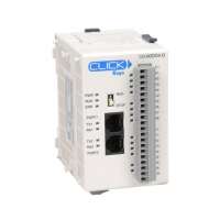
CLICK Basic and Standard PLCs have two built-in RS-232 ports. Both ports are 6-pin RJ12
phone type jacks. Port 1 communication parameters are fixed and is used primarily as the
programming port. Port 1 can also be used as a Modbus RTU protocol slave device. Port 2 is
a general purpose port, user configurable, with its communication parameters within CLICK
Programming Software, C0-PGMSW. Port 2 can be used as a Modbus RTU master or slave
protocol device, or handle ASCII data In or Out (ASCII stands for American Standard Code
for Information Interchange and defines a character encoding method for text that is used
in computers and other communication devices. Details can be found by doing a search for
ASCII on the internet).
Standard and Analog PLC versions also have a 3-pin RS-485 port, Port 3. Like Port 2, Port 3
is a general purpose port with its communication parameters being user configurable from the
programming software. Port 3 can be used as a Modbus RTU master or slave protocol device,
or handle ASCII data In or Out.
CLICK Ethernet Basic, Standard and Analog PLC units have one built-in Ethernet
communications port and one RS-232 serial communication port. Additionally, Ethernet
Standard and Analog PLC units have an RS-485 port.
The CLICK PLC can be networked to other CLICK PLCs, data input devices (barcode readers,
weight scales, etc.), and/or data output devices (serial printers, serial text displays, etc.). It is
also possible to network the CLICK PLC to other 3rd party PLCs and devices that have the
ability to communicate using the Modbus RTU protocol.
The final part of the PLC Communications chapter contains explanations and examples of the
various ways the Send and Receive programming instructions can be used to perform Modbus
RTU protocol and ASCII data communications between devices.
There are three different data addressing types that can be selected when using the Modbus
RTU protocol from the Send and Receive instructions. They are, CLICK addressing, Modbus
984 addressing, or Modbus HEX addressing. The CLICK addressing makes it convenient
to exchange data between CLICK PLCs. The other addressing choices are selected based on
the Modbus protocol addressing the networked devices are using. For details on the Modbus
protocol, visit www.modbus.org.
NOTE: The Modbus RTU Master is identified as the device that controls the exchange of data between
itself and any connected slave device. There can only be one master on the network. When the CLICK
PLC is the master, it is easily identified. It will be the PLC in the network with the Send and/or Receive
instructions using the Modbus protocol in its ladder logic program.
CLICK PLC Hardware User Manual, 6th Edition, Rev. F – C0-USER-M
4–2
Chapter 4: PLC Communications

 Loading...