CH1-CH4 Analog Terminals
24 VDC Input Power Terminal
OV (all OV commons are connected internally)
OV (all OV commons are connected internally)
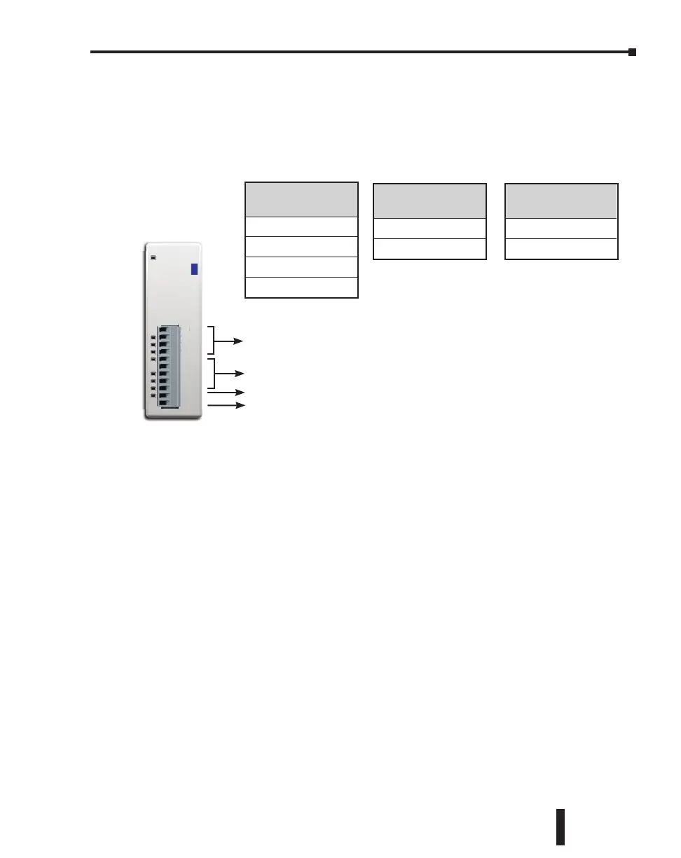
Terminal Block Wiring - Expansion Analog I/O Modules
The terminal block wiring will vary depending on which analog I/O module is being used. For
example, the C0-04AD-1 module shown here has four analog terminals, CH1 through CH4,
which are all current inputs.
See Chapter 2. Specifications for terminal block wiring diagrams and specifications for all the
analog I/O modules.
CH1
CH2
CH3
CH4
0V
0V
0V
0V
0V
24V
0V
C0-04AD-1
0-20mA
INPUT
H
CH
H
H
0
4
-
m
NPU
C0-04AD-1
Analog Input Modules
C0-04AD-1
C0-04AD-2
C0-04RTD
C0-04THM
Analog Output
Modules
C0-04DA-1
C0-04DA-2
Analog Combo
I/O Modules
C0-4AD2DA-1
C0-4AD2DA-2
CLICK PLC Hardware User Manual, 5th Edition, Rev. F – C0-USER-M
3–39
Chapter 3: Installation and Wiring

 Loading...