Installing the CLICK PLC
Connecting the Modules Together
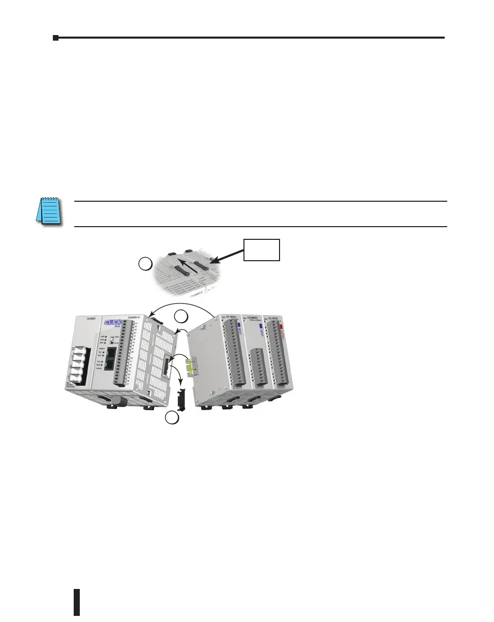
CLICK PLCs and I/O modules connect together using the Extension Ports that are located
on the side panels of the modules. The modules secure together by sliding LOCK/UNLOCK
latch tabs located on the top and bottom panels of the modules. A PLC backplane or base is
not required.
When connecting an I/O module to the PLC, first remove the Extension Port covers, slide
the latches forward (unlock), align the module pins, and press the I/O module onto the PLC’s
right side. Slide the latches backward to lock the modules together.
NOTE: If you are using other components in your system, make sure you refer to the appropriate manual to
determine how those units can affect mounting dimensions.
1
2
3
1) Remove extension port covers
and slide latch tabs forward.
2) Align the module pins and
connection plug, and press the
I/O module onto the right side
of the PLC.
3) Slide the latch tabs backward to
lock the modules together.
Latch
Tabs
CLICK PLC Hardware User Manual, 5th Edition, Rev. F – C0-USER-M
3–16
Chapter 3: Installation and Wiring

 Loading...