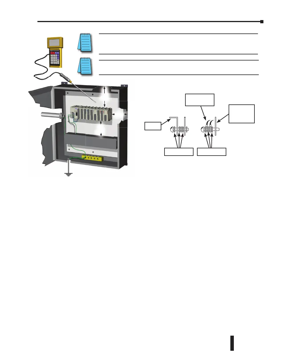
6. A good common ground reference (Earth ground) is essential for proper operation of the
CLICK PLC. One side of all control and power circuits and the ground lead on flexible
shielded cable must be properly connected to Earth ground. There are several methods of
providing an adequate common ground reference, including:
a) Installing a ground rod as close to the panel as possible
b) Connection to incoming power system ground
7. Evaluate any installations where the ambient temperature may approach the lower or
upper limits of the specifications. If you suspect the ambient temperature will not be
within the operating specification for the CLICK PLC system, measures such as installing
a cooling/heating source must be taken to get the ambient temperature within the range of
specifications.
8. CLICK PLC systems are modular and can be powered by any suitable 24VDC power
supply. The optional CLICK power supply is designed to attach to the left side of the
CLICK PLC case. CLICK power supplies accept 85-264 VAC and produce nominal
24VDC to power the CLICK PLC and I/O modules. Powerline filters are recommended for
protecting the CLICK PLC from power surges and EMI/RFI noise. The AutomationDirect
Powerline Filter, for use with 120VAC and 240VAC, 1–5 Amps, is an excellent choice
(locate at www.automationdirect.com), however, you can use a filter of your choice. The
filter units install easily between the AC power source and the PLC.
2 in.
50.8 mm
minimum
3 in.
76.2 mm
minimum
2 in.
50.8 mm
minimum
i
.
m
n
NOTE: There is a minimum clearance requirement of 2” (51mm) between the
CLICK PLC and the panel door or any devices mounted in the panel door. The
same clearance is required between the PLC and surrounding enclosure.
NOTE: A minimum clearance of 3” (76mm) is required between the PLC and a
wireway or any heat producing device.
Panel or
Single Point
Ground
Ground Braid
Copper Lugs
Star Washers
Star Washers
Panel
CLICK PLC Hardware User Manual, 5th Edition, Rev. F – C0-USER-M
3–15
Chapter 3: Installation and Wiring

 Loading...