PLC unit Troubleshooting
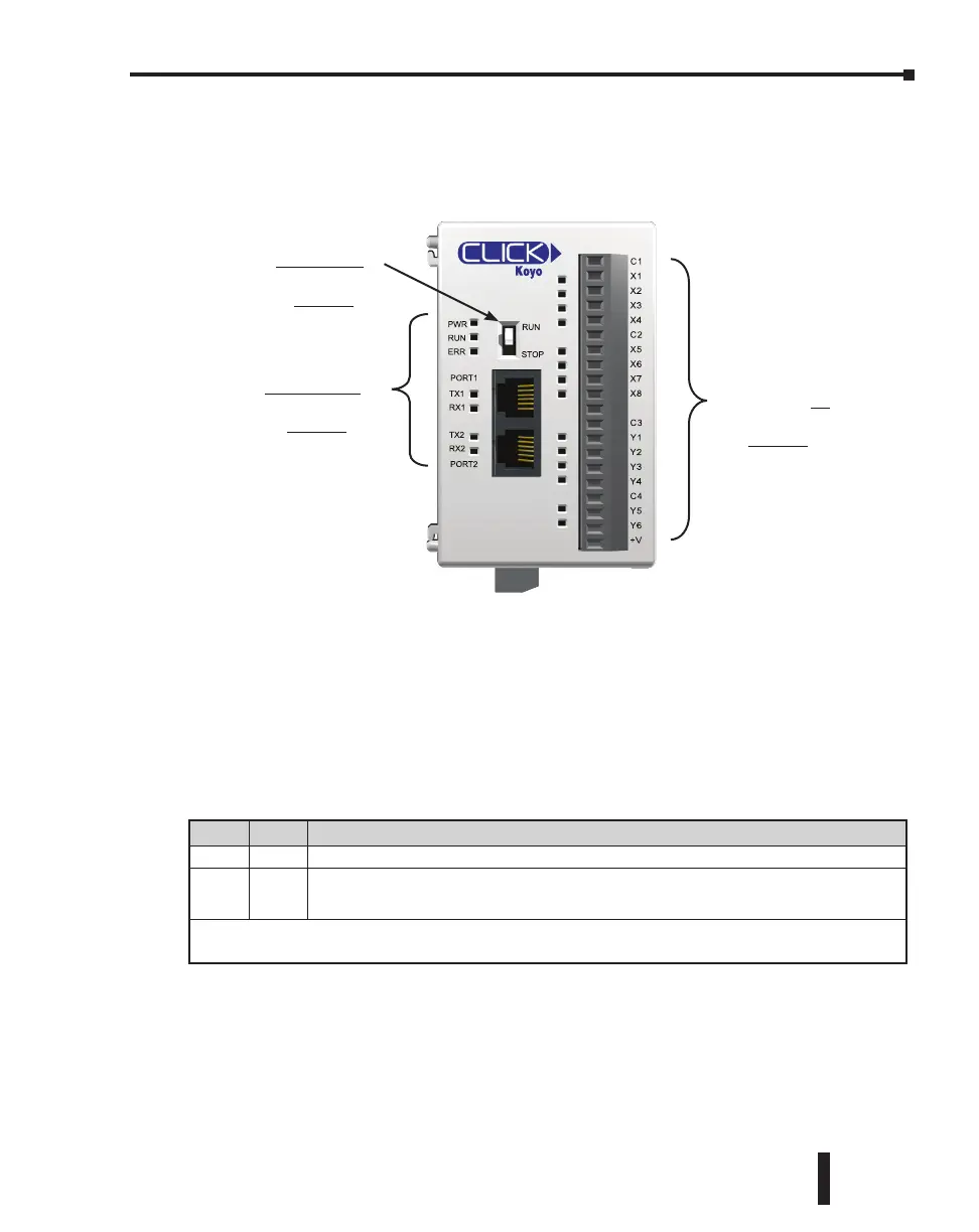
PLC unit issues are grouped according to their function. Use the illustration below to find the
appropriate document page numbers for issues with different PLC unit functions.
Toggle Switch
Switch is in RUN position
When the toggle switch is in the RUN position, the PLC unit should normally be in Run
mode (indicated by the RUN LED being ON), unless the PLC has been placed in Stop mode
by a peripheral device through one of the communication ports. To put the PLC unit in Run
mode, move the toggle switch to the STOP position and then switch it back again to the RUN
position. If the RUN LED then remains off, check the PWR and ERR LED indicators per the
chart shown below.
Switch is in STOP position
When the toggle switch is in STOP position, the PLC unit should be in Stop mode (indicated
by the RUN LED being OFF). Cycle power to the PLC. If the PLC unit starts up in Run
mode, with toggle switch in STOP position, it means the PLC unit does not recognize the
toggle switch position correctly. Please replace the PLC unit.
C0-00DD1-D
Problem with
toggle switch?
Go to
Page 6-3
Problem with
LED indicators?
Go to
Page 6-4
Problem with I/O?
Go to
Page 6-6
LED Status* Necessary action
PWR OFF There is insufficient power for the PLC unit. Check the power cable and input voltage.
ERR ON
There is an error in the PLC unit. Connect the CLICK programming software to read the
error information. See the “Error Codes” section at the end of this chapter for error message
instructions.
* If you see LED indications different from the ones shown in this table, refer to the “LED Indicators Troubleshooting”
section for further explanations.
CLICK PLC Hardware User Manual, 6th Edition, Rev. F – C0-USER-M
6–3
Chapter 6: Troubleshooting

 Loading...