CLICK I/O Modules
Several different types of input and output modules are available for the CLICK PLC system.
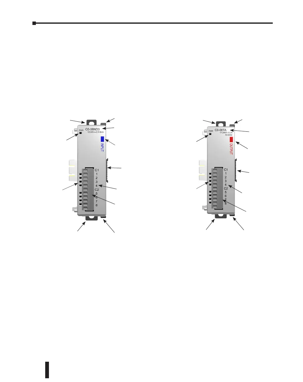
Please see the diagrams below to familiarize yourself with the I/O module features.
Each I/O module is identified as an Input or Output module on its front panel using the color
coding scheme listed below. Up to eight I/O option modules can be connected to a CLICK
PLC. See Mounting Guidelines in this chapter for module dimensions and Chapter 2 for
CLICK I/O module specifications.
Module Input
Point Identifier
Input Modules
Input Point
Status Indicators
(Green: ON)
Module
Part Number
Module Type
(Blue: Input)
Removable
Terminal Block
Power Indicator
(Green: Module Power Good)
Output Modules
Module Output
Point Identifier
Output Point
Status Indicators
(Red: ON)
Module
Part Number
Module Type
(Red: Output)
Removable
Terminal Block
Power Indicator
(Green: Module Power Good)
Sliding Latch
Sliding Latch
Sliding Latch
Sliding Latch
Mounting Tab
Mounting Tab
Mounting Tab
Mounting Tab
DIN Rail Slot and
I/O Module Port
Extension
DIN Rail Slot and
I/O Module Port
Extension
CLICK PLC Hardware User Manual, 5th Edition, Rev. F – C0-USER-M
3–8
Chapter 3: Installation and Wiring
 Loading...
