Output Module Troubleshooting
The output modules (including the PLC built-in outputs) can have the following symptoms:
How to Check the I/O Configuration
You can use the CLICK programming software to check the I/O configuration that the PLC
is recognizing:
• Connect the PLC to a computer running the CLICK programming software.
• From the software menus, connect the software to the
PLC by selecting PLC and Connect...
• From the software menus, select Setup and System Configuration...
• The System Configuration Setup window opens, and displays all of the CLICK
module types the PLC recognizes that are connected in the PLC system.
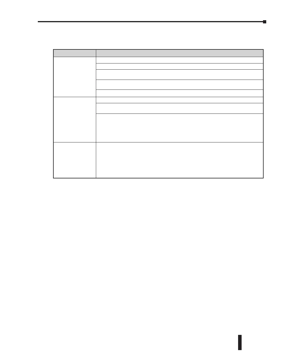
Symptom Necessary Action
The module LED
indicator is ON, but
there is no output.
Check the external power input voltage on the terminal block.
Check whether the terminal block is attached correctly.
If it is a DC sinking, relay, or AC output, check the voltage between the output and the
common. If the output is working correctly, the voltage should be close to zero.
If it is a sourcing output, check the voltage between the output and the 24 VDC input.
If the output is working correctly, the voltage should be close to zero.
If the LED indicator is ON, but the output voltage is not correct, replace the output module.
The module LED
indicator is OFF, even
though the output
status bit (Y---) is
supposed to be ON.
Check whether the PLC unit RUN LED is ON. If not, put the PLC in RUN mode.
Check the I/O configuration with the programming software.
(See “How to Check the I/O Configuration” below.)
Connect the programming software and check whether the Y bit related to the output point
is ON.
If the Y bit is not actually ON, use the override feature to manually turn the Y bit ON.
(See “How to Check the I/O Status” on the next page.)
If the Y bit is ON, but the output is OFF, replace the output module.
The module LED
indicator is OFF, but
the output is sending
an ON signal to the
field device.
Leakage current can be a problem when connecting field devices to I/O modules. False input
signals can be generated when the leakage current of the output point is great enough to turn
on the connected input device.
To correct this issue, install a resistor in parallel with the input or output of the circuit. The
value of this resistor will depend on the amount of leakage current and the voltage applied,
but usually a 10k to 20k ohm resistor will work. Ensure that the wattage rating of the resistor
is correct for your application.
CLICK PLC Hardware User Manual, 6th Edition, Rev. F – C0-USER-M
6–7
Chapter 6: Troubleshooting

 Loading...