Step 6: Establish PC to PLC Communications (cont’d)
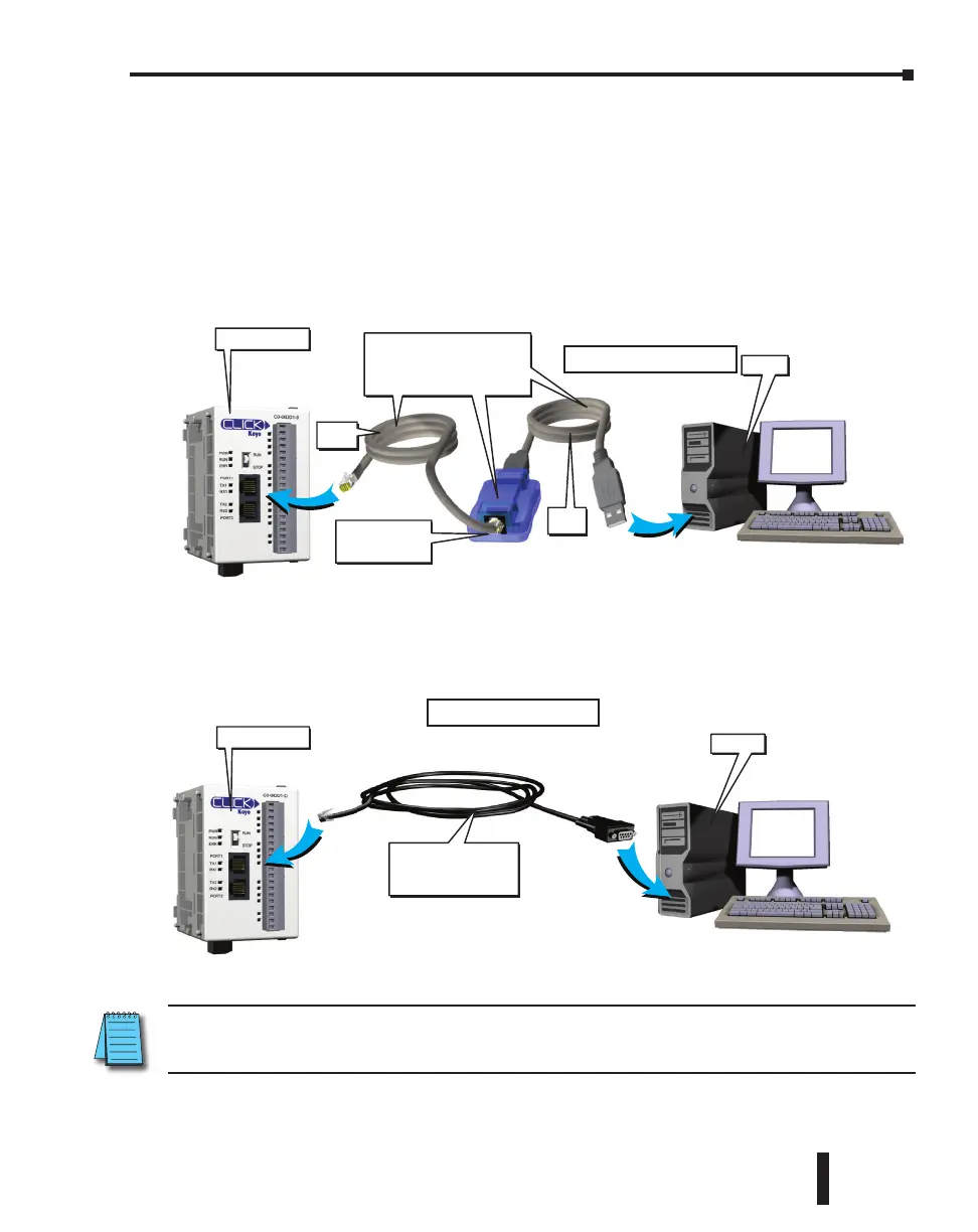
Using an RS-232 port for Programming
EITHER
If a USB port is available on the PC, then use an AutomationDirect USB to RS232 PC to Panel
Programming Cable Assembly (P/N - EA-MG-PGM-CBL) to connect between the USB port
on the PC and the RJ12 connector on the PLC’s Port 1.
OR
If a 9-pin RS-232 serial communications port is available on the PC, then use an
AutomationDirect PC Serial Programming Cable (P/N - D2-DSCBL) to connect between the
9-pin port on the PC and the RJ12 connector on the PLC’s Port 1.
NOTE: Port 1 (RS-232) on the CLICK PLC unit is designed as the primary programming port. The port has
fixed communication parameters, so you can always connect the programming software to the CLICK PLC
unit through the port without any configuration changes.
CLICK PLC
PC
PC Serial
Programming Cable
D2-DSCBL
Using a PC Serial Port.
PC
Serial
Cable
CLICK PLC
USB
Cable
USB to RS232
Converter
PC to Panel Programming
Cable Assembly
(Includes serial & USB cables)
EA-MG-PGM-CBL
Using a PC USB Port.
CLICK PLC Hardware User Manual, 6th Edition, Rev. G – C0-USER-M
1–17
Chapter 1: Getting Started

 Loading...