PLC’s Integrated Transient Suppressors
Although the PLC’s outputs typically have integrated suppressors to protect against transients,
they are not capable of handling them all. It is usually necessary to have some additional
transient suppression for an inductive load.
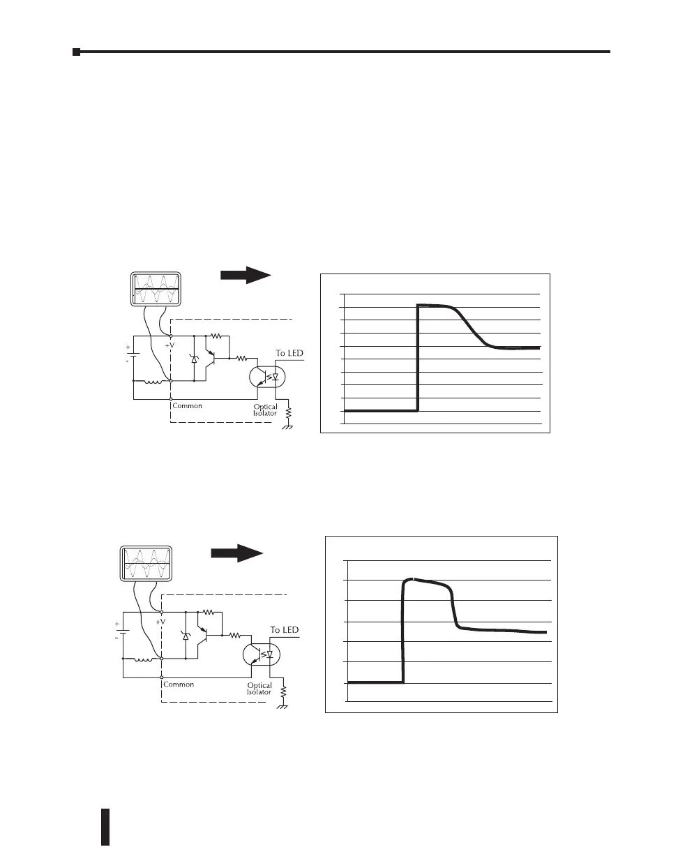
Here is another example using the same 24V, 125mA, 3W relay used earlier. This example
measures the PNP transistor output of a D0-06DD2 PLC, which incorporates an integrated
Zener diode for transient suppression. Instead of the 140V peak in the first example, the
transient voltage here is limited to about 40V by the Zener diode. While the PLC will probably
tolerate repeated transients in this range for some time, the 40V is still beyond the module’s
peak output voltage rating of 30V.
5HOD\�
&RLO�
��
9'&
��)RU�WKLV�H[DPSOH��D���9����P$��:�
UHOD\�LV�XVHG��$XWRPDWLRQ'LUHFW�
SDUW�QR�������&���'�
��
��
��
��
��
��
�
��
9ROWV
��
��
�
Example: Small Inductive Load with Only Integrated Suppression
The next example uses the same circuit as above, but with a larger 24V, 290mA, 7W relay
thereby creating a larger inductive load. As you can see, the transient voltage generated is much
worse, peaking at over 50V. Driving an inductive load of this size without additional transient
suppression is very likely to permanently damage the PLC output.
Example: Larger Inductive Load with Only Integrated Suppression
5HOD\�
&RLO�
��
9'&
��)RU�WKLV�H[DPSOH��D�������P$��:�
UHOD\�LV�XVHG��$XWRPDWLRQ'LUHFW�
SDUW�QR��6&�(��*���9'&�
��
��
��
��
��
��
�
���
9ROWV
Additional transient suppression should be used in both these examples. If you are unable
to measure the transients generated by the connected loads of your control system, using
additional transient suppression on all inductive loads would be the safest practice.
CLICK PLC Hardware User Manual, 5th Edition, Rev. F – C0-USER-M
3–34
Chapter 3: Installation and Wiring

 Loading...