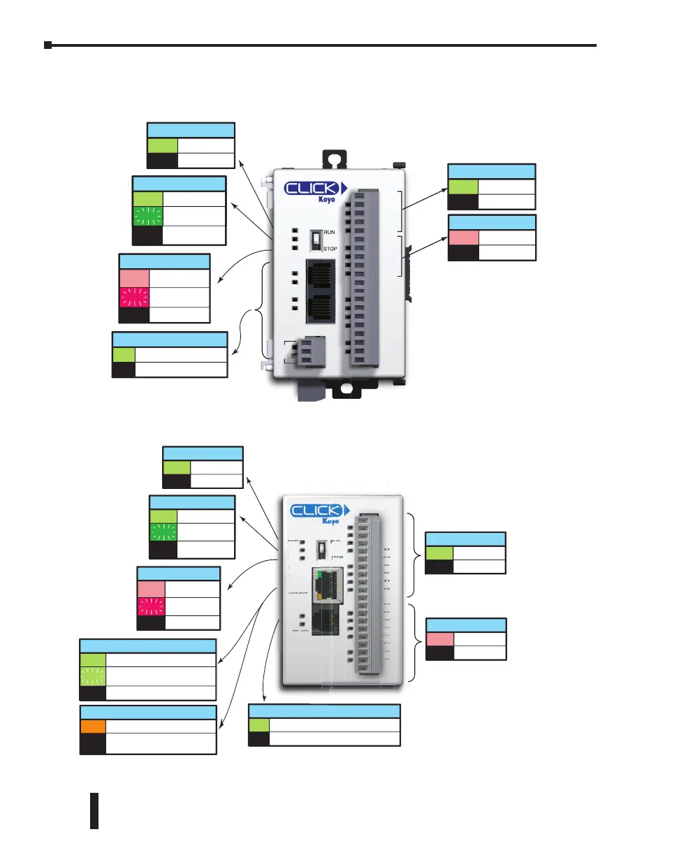
PLC LED Status Indicators, (cont’d)
C0-02DD1-D
C1
X1
X2
X3
X4
C2
Y1
Y2
Y3
Y4
+V
AD1V
AD1I
AD2V
AD2I
ACOM
DA1V
DA1I
DA2V
DA2I
RS-485
PORT3
PORT2
PORT1
PWR
RUN
ERR
TX2
RX2
TX1
RX1
TX3
RX3
INPUT LEDs (Green)
On Input True
Input FalseOff
OUTPUT LEDs (Red)
On Output True
Output FalseOff
Analog PLCs
TX & RX LED (Green)
On Comm Port Data Active
No CommunicationOff
POWER LED (Green)
On Power Good
Power FailureOff
RUN LED (Green)
On PLC Run Mode
Initializing
System
PLC Program
Mode
Off
Blink
ERROR LED (RED)
On
Self Diagnostic
Error
Self Diagnostic
Warning
No ErrorOff
Blink
Analog PLC
C0-10DD1E-D
C1
X1
X2
X3
X4
C2
X5
X6
X7
X8
C3
Y1
Y2
Y3
Y4
C4
Y5
Y6
+V
LNK/ACT
PORT1
PWR
RUN
ERR
RUN
STOP
PORT2
RS-232
TX2
RX2
100MBIT
ETHER
NET
INPUT LEDs (Green)
On Input True
Input FalseOff
OUTPUT LEDs (Red)
On Output True
Output FalseOff
Ethernet Basic PLC
POWER LED (Green)
On Power Good
Power FailureOff
RUN LED (Green)
On PLC Run Mode
Initializing
System
PLC Program
Mode
Off
Blink
ERROR LED (RED)
On
Self Diagnostic
Error
Self Diagnostic
Warning
No ErrorOff
Blink
Blink
LNK/ACT LED (Green)
On Connected to the network
Communicating
Disconnected from the network
100MBIT LED (Orange)
On
Communicating at 100Mbps
Communicating at 10Mbps or
disconnected from the network
Off
Off
TX and RX (Green)
On The Comm Port is sending data.
The Comm Port is not sending data.Off
+
Ethernet Basic PL
D1E
-1
D
P
RT
-
TX
RX
ETHE
NK
A
P
RT
ER
Ethernet Basic PLC
CLICK PLC Hardware User Manual, 6th Edition, Rev. G – C0-USER-M
2–30
Chapter 2: Specifications
 Loading...
