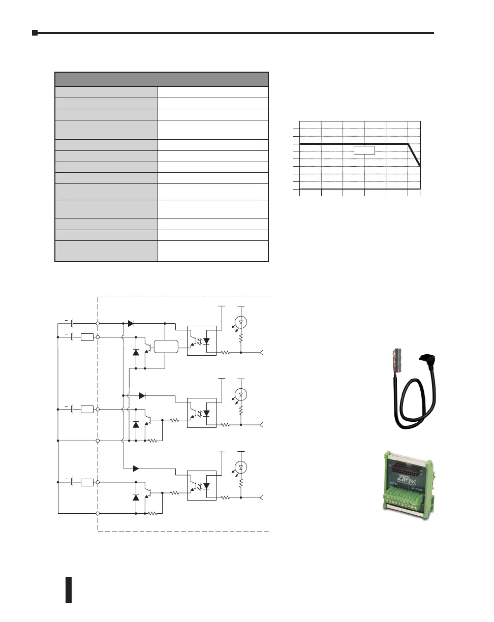
C0-00DD1-D – 8 DC Input/6 Sinking DC Output Micro PLC (continued)
OUTPUT
Y2-Y4
C3
L
5 - 27 VDC
Internal Module Circuitry
Optical Isolator
Equivalent Output Circuit
+
OUTPUT
Y5-Y6
C4
L
5 - 27 VDC
Optical Isolator
+
Note: C3 & C4 are not internally connected.
COM
COM
OUTPUT
Y1
L
5 - 27 VDC
Optical Isolator
+
24 VDC
+V
+
High response
circuit
C0-00DD1-D
* Zener Diode Power Dissipation: 200 mW
*
*
*
ZIPLink Pre-Wired PLC Connection
Cables and Modules for CLICK PLC
20-pin connector cable
ZL-C0-CBL20 (0.5 m length)
ZL-C0-CBL20-1 (1.0 m length)
ZL-C0-CBL20-2 (2.0 m length)
0
Surrounding Air Te mperature (°C/°F)
32
10
50
20
68
30
85
40
104
50
122
55 °C
131 °F
2
4
6
8
Points
C0-00DD1-D Temperature Derating Chart
0
* Use every other output.
Outputs
*
ZL-RTB20
20-pin feed-through
connector module
Built-in I/O Specifications - Outputs
Outputs per Module
6 (Sink)
Operating Voltage Range
5–27 VDC
Output Voltage Range
4–30 VDC
Maximum Output Current
0.1 A/point; C3: 0.4 A/common,
C4: 0.2 A/common
Minimum Output Current
0.2 mA
Maximum Leakage Current
0.1 mA @ 30.0 VDC
On Voltage Drop
0.5 VDC @ 0.1 A
Maximum Inrush Current
150mA for 10ms
OFF to ON Response
Y1: typ 5μs; Max 20μs
Y2-6: < 0.5 ms
ON to OFF Response
Y1: typ 5μs; Max 20μs
Y2-6: < 0.5 ms
Status Indicators
Logic Side (6 points, red LED)
Commons
2 (4 points/com & 2 points/com)
External DC Power
Required
20–28 VDC Maximum @ 60mA
(All Points On)
CLICK PLC Hardware User Manual, 6th Edition, Rev. G – C0-USER-M
2–36
Chapter 2: Specifications