4-38 BE1-951 Protection and Control 9328900990 Rev L
Operating Settings for Phase Undervoltage/Overvoltage
Operating settings for the 27P and 59P functions consist of pickup and time delay values. The pickup
value determines the level of voltage required for the element to start timing toward a trip. The time delay
value determines the length of time between pickup and trip. Time delays can be set in milliseconds,
seconds, or cycles. The default is milliseconds if no unit of measure is specified.
Operating settings are made using BESTCOMS.
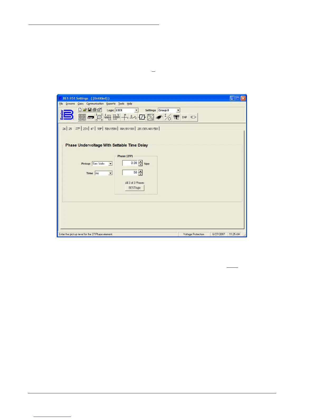
Figure 4-31 illustrates the BESTCOMS screen used to
select operational settings for the undervoltage element. The overvoltage element is on the 59P tab. To
open the screen, select Voltage Protection from the S
creens pull-down menu and select the 27P or 59 P
tab. Alternately, settings may be made using the S<g>-27P and S<g>-59P ASCII command or through
the HMI using Screens 5.x.3.1 and 5.x.8.1 where x equals the setting group number.
Figure 4-31. Voltage Protection Screen, 27P Tab
At the top center of the screen is a pull-down menu labeled Logic. This menu allows viewing of the
BESTlogic settings for each preprogrammed logic scheme. A custom logic scheme must
be created and
selected in the Logic pull-down menu at the top of the screen before BESTlogic settings can be changed.
See Section 7, BESTlogic Programmable Logic. To the right of the Logic pull-down menu is a pull-down
menu labeled Settings. The Settings menu is used to select the setting group that the elements settings
apply to.
The default unit of measure for the Pickup, Alarm Threshold, and Inhibit settings is secondary amps.
Primary amps (Pri Amps), per unit amps (Per U Amps), and percent amps (% Amps) can also be selected
as the pickup setting unit of measure. The unit of measure for the Time setting that represents the
element's time delay defaults to milliseconds. It is also selectable for seconds, minutes, and cycles.
Using the pull-down menus and buttons, make the application appropriate settings to the undervoltage
and overvoltage elements.
Operating settings for Phase Undervoltage/Overvoltage are summarized in
Table 4-22.