9328900990 Rev L BE1-951 Protection and Control 4-7
Note the difference in operation when a switch-to threshold of 0% is used. For this setting the group is
switched to when current falls below 0.5 A / 0.1 A (5 A / 1 A nominal), but when any other switch level is
used, the switch occurs when current rises above the switch level.
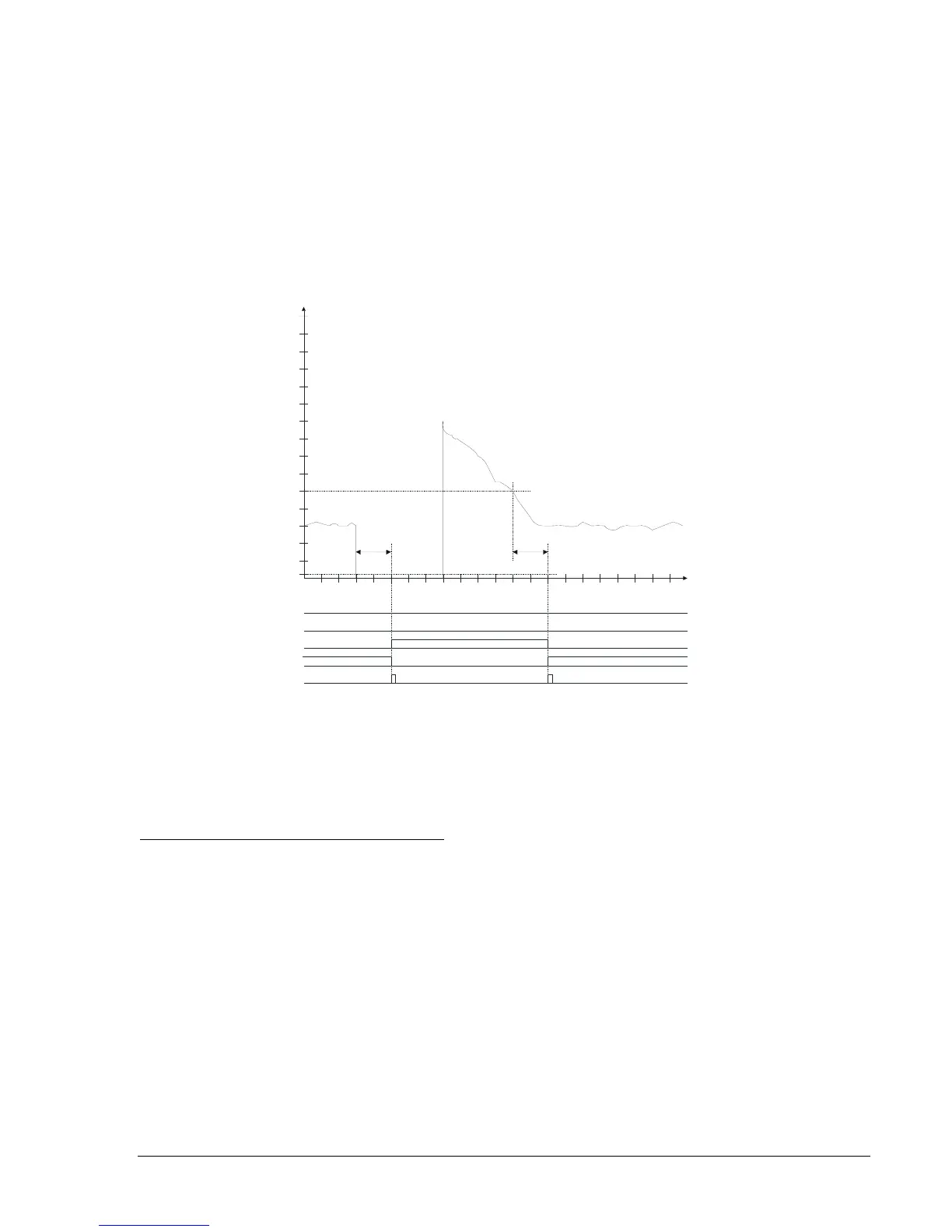
Figure 4-6 shows how the active setting group follows the load current and time delay settings for Setting
Group 1. Note that the AUTO input must be at a TRUE (1) logic state in order to allow the automatic logic
to operate. When the breaker opens, the load current falls to zero at time = 15 minutes. After 10 minutes,
Setting Group 1 becomes active and the setting group change output pulses TRUE. When the breaker is
closed at time = 40 minutes, load current increases to approximately 90 percent of pickup. As the load
current decreases to 50 percent of pickup, the Setting Group 1 return timer begins timing. After ten
minutes, Setting Group 1 output goes FALSE, the setting group returns to Setting Group 0 and the setting
group change output pulses TRUE.
SG
3
SG2
SG
1
SG0
oa
Current
as % of S0-51 <pickup>
40
30
20
10
100
90
80
70
60
50
120
110
140
130
150
SP-GROUP1=10, 0, 10, 50, 51P
10 10
SP-GROUP3=0,0,0,0,0
SP-GROUP2=0,0,0,0,0
0
9080
70
6050
40
30
2010
100
TIM
E
(MINUTES
)
0
(0.5A
)
D2840-22
05-05-04
Figure 4-6. Automatic Operation Based on Cold Load Pickup
When the switch to criteria is met for more than one setting group at a time, the function will use the
numerically higher of the enabled settings groups. If the switch to time delay setting is set to 0 for a
setting group, automatic control for that group is disabled. If the return time delay setting is set to 0 for a
setting group, automatic return for that group is disabled and the relay will remain in that settings group
until returned manually by logic override control.
Group Control by Monitoring Reclose Status
The active setting group may also be controlled by the status of the reclose (79) function. Upon entering a
reclose operation, as the relay steps through an automatic reclose operation, the relay may be instructed
to change to an appropriate setting group using the command SP-GROUP[n] = ,,,,<791, 792, 793, or
794>. If the monitored element in the SP-GROUP command is 791, 792, 793, or 794, the switch-to time,
switch-to threshold, return time, and return threshold are ignored.
When settings group changes are made via SP-GROUP[n] = ,,,,<791, 792, 793, or 794> the relay will
stay in the last group changed to till the relay returns to reset condition. Upon return to reset condition, the
relay restores Setting Group 0. The settings group changes via SP-GROUP[n] = ,,,,<791, 792, 793 794>
can only raise setting a group number. For instance, one cannot have reclose 1 change to Setting Group
2 and then reclose 2 change to Setting Group 1. When reclose 2 occurs, the relay will remain in Setting
Group 2.
The points in the reclose process that the 791, 792, 793, and 794 setting causes a change to the desired
setting group is when a) the referenced reclose occurs and b) after the breaker closes. For instance, SP-
GROUP1 = ,,,,791 will cause the relay to change from Setting Group 0 to Setting Group 1 after the first
reclose, but not until the relay senses the breaker has actually closed. This may be best understood by
examining the diagram in the following example.