3-8 BE1-951 Input and Output Functions 9328900990 Rev L
∗ Since the input conditioning function is evaluated every quarter cycle, the setting is internally rounded to
the nearest multiple of 4.16 milliseconds (60 Hz systems) or 5 milliseconds (50 Hz systems).
If you are concerned about ac voltage being coupled into the contact sensing circuits, the recognition time
can be set for greater than one-half of the power system cycle period. This will take advantage of the half-
wave rectification provided by the input circuitry.
If an ac wetting voltage is used, the recognition time can be set to less than one-half of the power system
cycle period and the debounce timer can be set to greater than one-half of the power system cycle
period. The extended debounce time will keep the input energized during the negative half-cycle. The
default settings of 4 and 16 milliseconds are compatible with ac wetting voltages.
Digital input conditioning settings are entered through the communication ports using the SG-IN (setting
general-input) command.
Retrieving Input Status Information from the Relay
Input status is determined through BESTCOMS by selecting Metering from the R
eports pull-down menu
and selecting the Start Polling button in the lower right hand corner of the screen. Alternately, status can
be determined through HMI Screen 1.5.1 or through the communication ports using the RG-STAT (report
general-status) command. See Section 6, Reporting and Alarm Functions, General Status Reporting, for
more information.
OUTPUTS
BE1-951 relays have five general-purpose output contacts (OUT1 through OUT5) and one fail-safe,
normally closed/open (when de-energized), alarm output contact (OUTA). Each output is isolated and
rated for tripping duty. OUT1 through OUT5 are Form A (normally open), and OUTA is Form A or B
(normally closed/open depending on style number). A trip coil monitoring circuit is hardwired across
OUT1. See Section 6, Reporting and Alarm Functions, Trip Circuit Monitoring, for details.
Hardware Outputs and Virtual Outputs
Output contacts OUT1 through OUT5 and OUTA are driven by BESTlogic expressions for VO1 through
VO5 (Virtual Outputs 1 through 5) and VOA (Virtual Output A). The use of each output contact is
completely programmable so you can assign meaningful labels to each output and to the logic 0 and logic
1 states of each output. Section 7, BESTlogic Programmable Logic, has more information about
programming output expressions in your programmable logic schemes.
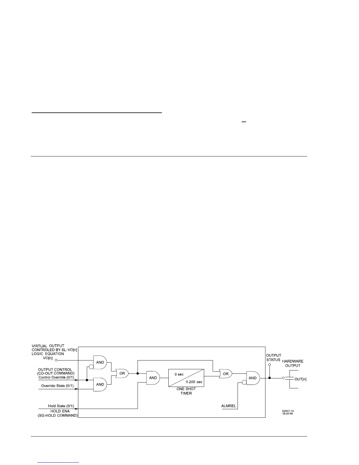
A virtual output (VOn) exists only as a logical state inside the relay. A hardware output is a physical
output relay contact. BESTlogic expressions for VO1 through VO5 (Virtual Outputs 1 through 5) and VOA
(Virtual Output A) drive Output Contacts OUT1 through OUT5 and OUTA. The state of the output contacts
can vary from the state of the output logic expressions for three reasons:
a. The relay trouble alarm disables all hardware outputs.
b. The programmable hold timer is active.
c. The select-before-operate function overrides a virtual output.
Figure 3-5 shows a diagram of the output contact logic for the general-purpose output contacts. Figure
3-6 illustrates the output contact logic for the fail-safe alarm output contact.
Figure 3-5. Output Logic, General Purpose Output Contacts