9328900990 Rev L BE1-951 Installation 12-15
RELAY CONNECTIONS
Connections to the relay are dependent on the application and logic scheme selected by the user. As a
result, all of the relay's inputs and outputs may not be used for a given application. Before energizing a
relay, make sure the connections match the options associated with the model and style number found on
the relay nameplate. Refer to the Style Chart in Section 1 for options. Be sure to use the correct input
power for the specified power supply. Incorrect wiring may result in damage to the relay.
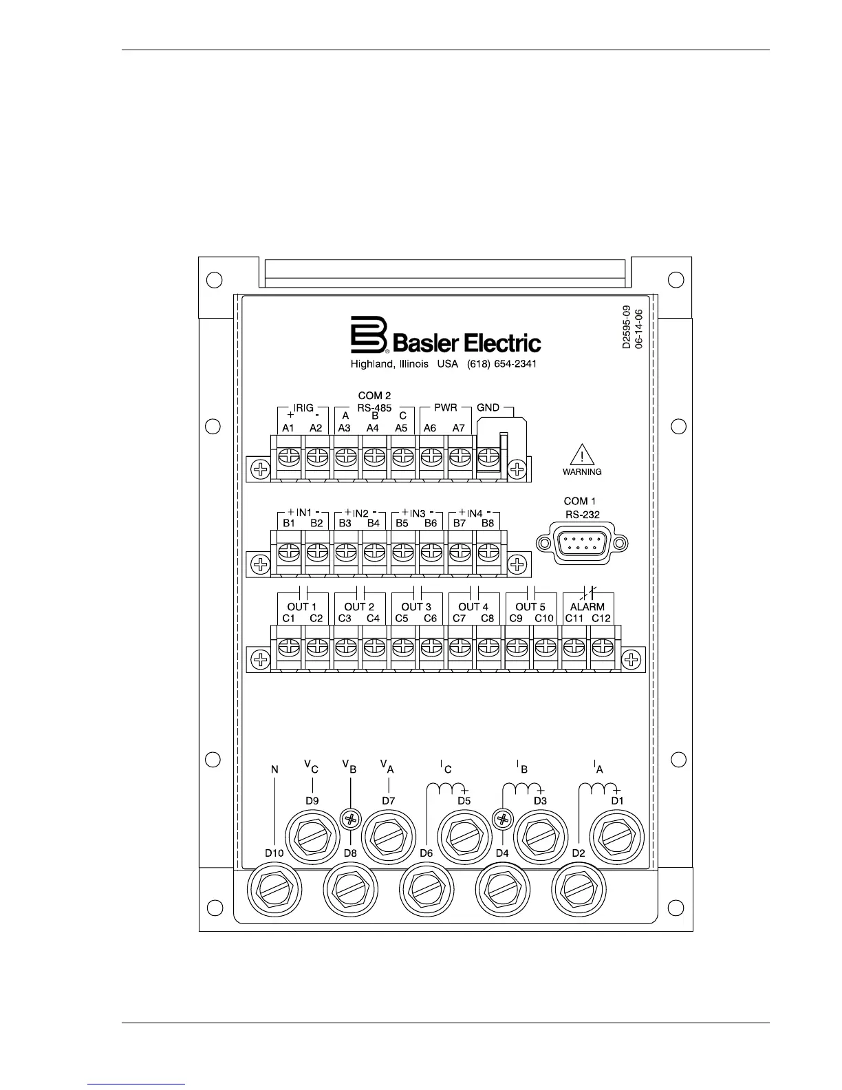
Figures 12-15 and 12-16 show the terminal connections located on the rear-panel of an S1 and S1
Double-ended style case, respectively.
Figure 12-17 shows the rear-panel connections for an H1 style
case.
Figure 12-15. S1 Rear Panel Terminal Connections