13-16 BE1-951 Testing and Maintenance 9328900990 Rev L
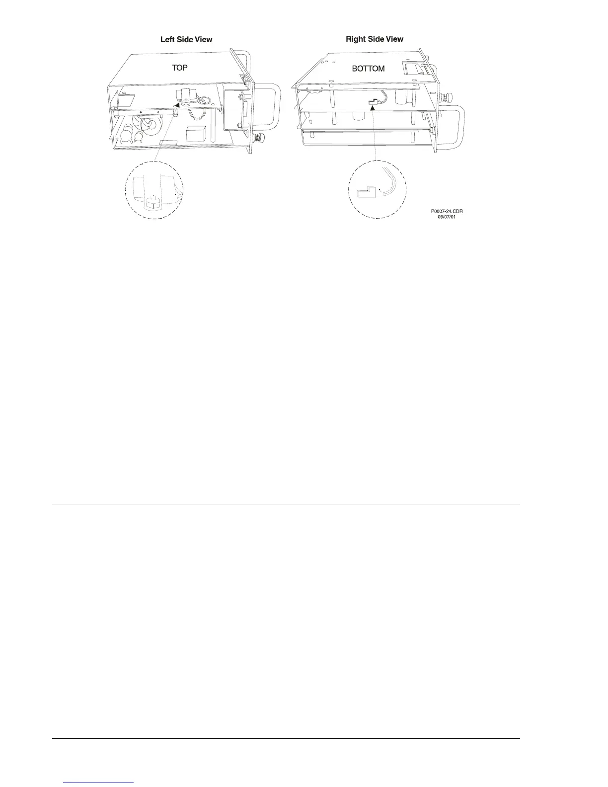
Figure 13-4. Backup Battery Location
Step 4: Insert the new battery by carefully feeding the leads through the hole in the aluminum plate and
sliding them between the PC boards. Plug the new battery into the connector as shown in
Figure 13-4.
Step 5: Place the battery under the battery strap and replace the nut. Put the unit back into the case.
To Replace Battery in S1 Case
Step 1: Remove the unit from the case.
Step 2: Remove the front panel from the unit by removing the four screws located in the upper, lower,
left and right hand corners. The battery will be attached to the backside of the panel, using a
strap similar to what is shown for the H1 case in
Figure 13-4.
Step 3: Disconnect the battery cable from the connector on the right side of the unit. Caution: Be sure
that all static body charges are neutralized before touching the PC board.
Step 4: Using a 5/16" nut driver, remove the nut holding the battery strap in place. Then remove the old
battery being careful not to hang the leads on the PC board components. Consult your local
ordinance for proper battery disposal.
Step 5: Insert the new battery and connect the lead to the connector the old battery had been
connected.
Step 6: Place the battery under the battery strap and replace the nut. Put the unit back into the case.
CARE AND HANDLING
The BE1-951 can be fully drawn out of the case. When the drawout assembly is removed, the current
transformer input circuits are automatically shorted by the case. The case contains no components that
are likely to require service; all critical components are contained in the drawout assembly. When
removing the drawout assembly from the case, care should be taken to prevent electrostatic discharge
(ESD) and mechanical damage.
There is no need to disturb the circuit interconnections within the drawout assembly. Repair of the
drawout assembly by replacement of individual circuit boards is not recommended. The printed circuit
boards are constructed using surface-mount technology and are not intended to be field serviceable.
If a relay failure occurs in a critical application without sufficient redundancy, protection can be restored
by inserting a spare relay in the mounted and wired case of the relay requiring service. The drawout
assembly requiring service can then be returned to the factory in the case from the spare relay. If a spare
case isn't available, care should be used when packing the drawout assembly for shipment. Use antistatic
packing material that prevents mechanical damage during transit.
Before returning the drawout assembly for repair, contact the Basler Electric Technical Services
Department at 618-654-2341 for a return authorization number.