4-72 BE1-951 Protection and Control 9328900990 Rev L
60FL
V1
8.8% Vnom
V2
25% V1
I2
17.7% I1
V1
8.8% Vnom
I1
200% Inom
I1
8.8% Inom
3w/4w Sensing
1 or 2 phase Fuse Loss
3 Phase Fuse Loss
A
C
D
F
B
G
E
H
N
60FL Output Latch
60FL Reset
K
L
M
85% Vnom
V1
P0002-26
03-22-04
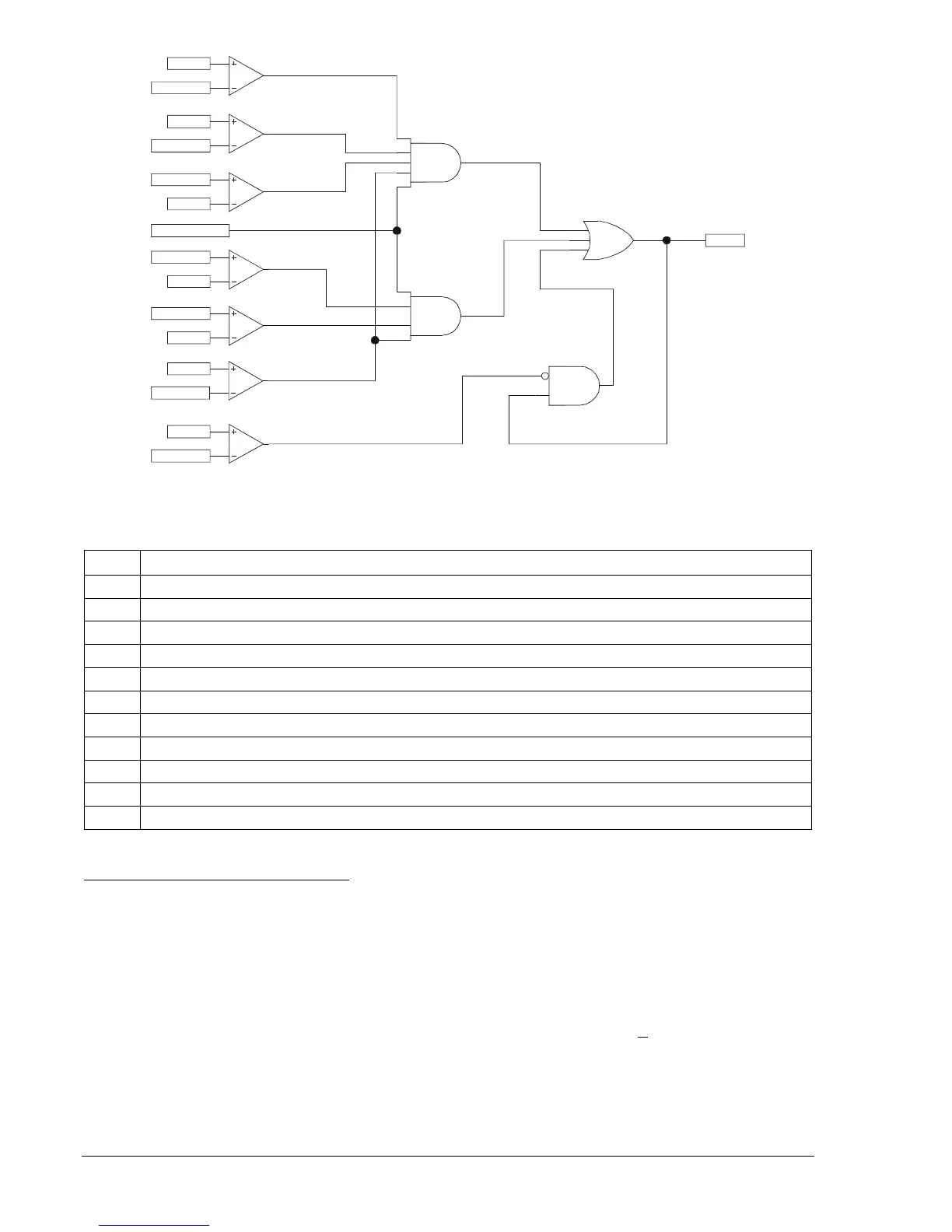
Figure 4-67. 60FL Element Logic
Table 4-41. 60FL Logic Parameters
Input TRUE Condition
A Positive-sequence volts greater than 8.8% of the nominal voltage; Detects minimum voltage is applied.
B Positive-sequence amps greater than 8.8% of the nominal current; Detects minimum current is applied.
C Negative-sequence volts greater than 25% of the pos-seq volts; Detects loss of 1 or 2 phase voltages.
D Negative-sequence amps less than 17.7% of the pos-seq amps; Detects a normal current condition.
E Positive-sequence volts less than 8.8% of the nominal voltage; Detects loss of 3-phase voltage.
F Positive-sequence amps less than 200% of the nominal current; Detects a normal load current condition.
G Three-wire or four-wire sensing selected.
H Positive-sequence volts greater than 85% of nominal voltage; Detects a restored voltage condition.
K (A * B * C * D * G); Detects when either one or two phases are lost.
L (E * F * B * G); Detects when all three phases are lost.
M, N Latches the 60FL output until the reset criteria are met.
Fuse Loss Detection Blocking Settings
The 60FL logic bit is always enabled regardless of the SP-60FL setting. User selectable block settings
determine how certain (not all) current and voltage protective functions operate when a fuse loss
condition exists (see
Table 4-42). The I Block setting (51/27R) assumes that the voltage is V
nom
when
60FL is TRUE because the voltage measurement is not present or is unreliable. If the input voltage is
nominal, then voltage restraint and control have no effect. The V Block setting (P, N, and Q) determines
which voltage functions are blocked when the 60FL logic is TRUE.
Settings are made using BESTCOMS.
Figure 4-68 illustrates the BESTCOMS screen used to select
blocking settings for the 60FL element. Select Reporting and Alarms from the S
creens pull-down menu
and select the VT Monitor tab. Alternately, settings may be made using the SP-60FL ASCII command.
See Section 11, ASCII Command Interface, Command Summary, Protection Setting Commands, for
more information.