13-42 BE1-951 Testing and Maintenance 9328900990 Rev L
Step 3: Prepare to monitor the 27X and 59X/159X function operation. Operation can be verified by
monitoring OUT1.
Step 4: Connect and apply a single-phase, 80 Vac, 3rd harmonic voltage source to Terminals C17
(polarity), and C18 (non-polarity). Refer to
Figure 13-1 for terminal locations.
Step 5: Slowly decrease the voltage until OUT1 closes. Pickup should occur within ±2 percent or 1 volt
of the pickup setting. Slowly increase the voltage until OUT1 opens. Dropout should occur
between 102 and 103 percent of the actual pickup value. Verify the 27-3 bus target on the HMI.
Step 6: Continue to increase voltage until OUT1 closes. Pickup should occur within ±2 percent or 1 volt
of the pickup setting. Slowly reduce the voltage until OUT1 opens. Dropout should occur
between 97% and 98% of the actual pickup value.
Step 7: Verify the pickup and dropout accuracy of the middle and upper pickup settings listed in
Table
13-59. Verify the 59-3 bus target on the HMI.
Step 8: (Optional.) Repeat Steps 2 through 7 for Setting Groups 1, 2, and 3.
Auxiliary Undervoltage/Overvoltage Timing Verification (3
rd
Harmonic Vx Input)
Step 1: Using
Table 13-60 as a guide (same values as the fundamental test but at 3rd harmonic
frequency), transmit the first row of setting commands to the relay.
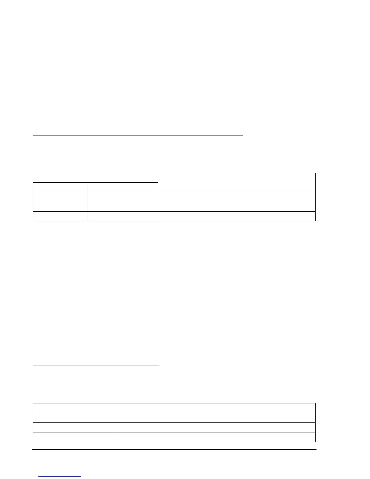
Table 13-60. 27X and 59X/159X Pickup and Time Delay Settings
Pickup and Time Delay Settings
Undervoltage Overvoltage
Purpose
S0-27X=50,2S S0-59X/159X=110,2S Sets 27X PU at 50 V, 59X/159X at 110 V, TD at 2 sec.
S0-27X=,5S S0-59X/159X=,5S Sets 27X PU at 50 V, 59X/159X at 110 V, TD at 5 sec.
S0-27X=,10S S0-59X159X=,10S Sets 27X PU at 50 V, 59X/159X at 110 V, TD at 10 sec.
Step 2: Prepare to monitor the 27X and 59X/159X timings. Timing accuracy is verified by measuring the
elapsed time between a sensing voltage change and OUT1 closing.
Step 3: Connect and apply a single-phase, 80 Vac, 3rd harmonic voltage source to Terminals C17
polarity), and C18 (non-polarity). Refer to
Figure 13-1 for terminal locations.
Step 4: Step the voltage down to 45 volts. Measure the time delay and verify the accuracy of the 27X
time delay setting. Timing accuracy is ±5 percent or ±3 cycles of the time delay setting.
Step 5: Step the voltage up to 115 volts. Measure the time delay and verify the accuracy of the
59X/159X time delay setting. Timing accuracy is ±5 percent or ±3 cycles of the time delay
setting.
Step 6: Repeat Steps 5 and 6 for the middle and upper time delay settings of
Table 13-60.
Step 7: (Optional.) Repeat Steps 2 through 6 for Setting Groups 1, 2, and 3.
Negative-Sequence Voltage (47)
Purpose: To verify the operating accuracy of the 47 protection element.
Reference Commands: SL-47, SL-VO, SL-GROUP, RG-STAT
Negative-Sequence Voltage Pickup Verification
Step 1: Prepare the 47 pickup function for testing by transmitting the commands in
Table 13-61 to the
relay. Reset targets.
Table 13-61. 47 Pickup Test Commands
Command Purpose
A= Gains write access.
SL-N=NONE Zero out custom logic settings. Overwrite with LOGIC=NONE settings.
Y Confirm overwrite.