9328900990 Rev L BE1-951 Testing and Maintenance 13-43
Command Purpose
SL-N=47 Sets 47 as custom logic name.
SL-27P=0 Disables 27P.
SL-59P=0 Disables 59P.
SL-47=1,0 Enables 47, disables blocking.
SP-60FL=ENA,PN Removes 60FL block from 47 element.
SL-VO1=47T Enables OUT1 to close for 47 trip.
SG-TRIG=47T,47PU,0 Enables 47 to log and trigger fault recording.
EXIT;Y Exit and save settings.
Step 2: Using
Table 13-62 as a guide, transmit the first row of setting commands to the relay.
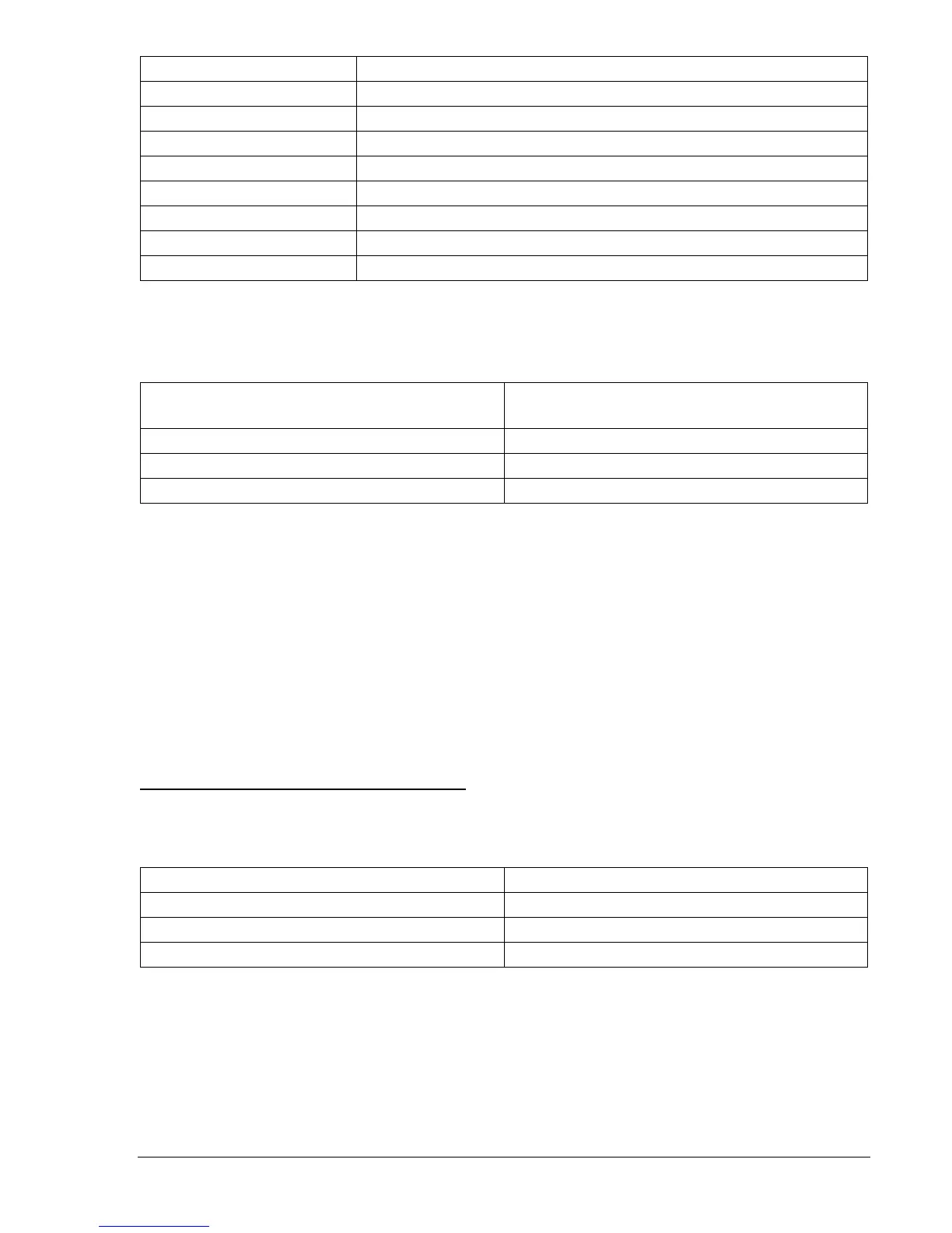
Table 13-62. 47 Pickup Settings
Pickup Settings
(Negative-Sequence Voltage)
Purpose
S0-47=24,50ms Sets 47 PU at 24 V, Time Delay at minimum.
S0-47=30,50ms Sets 47 PU at 30 V, Time Delay at minimum.
S0-47=36,50ms Sets 47 PU at 36 V, Time Delay at minimum.
Step 3: Prepare to monitor 47 function operations. Operation can be verified by monitoring OUT1.
Step 4: Connect and apply a 50 Vac, single-phase voltage source to Terminals C13 (A-phase) and C16
(Neutral). Refer to
Figure 13-1 for terminal locations.
Step 5: Negative-sequence voltage is the phase voltage; therefore for a V2 setting of 24 volts, the
applied phase voltage will be 24 x 3 or 72 volts. Slowly increase the A-phase voltage until OUT1
closes. Pickup should occur within ±2 percent or 1 volt of the pickup setting. Slowly decrease
the A-phase voltage until OUT1 opens. Dropout should occur between 97 and 98 percent of the
actual pickup value. Verify the 47 target on the HMI.
Step 6: Verify the pickup and dropout accuracy of the middle and upper 47 pickup settings.
Step 7: (Optional.) Repeat Steps 2 through 6 for the B-phase and C-phase voltage inputs.
Step 8: (Optional.) Repeat Steps 2 through 7 for Setting Groups 1, 2, and 3.
Negative-Sequence Voltage Timing Verification
Step 1: Using
Table 13-63 as a guide, transmit the first row of setting commands to the relay.
Table 13-63. 47 Pickup and Time Delay Settings
Pickup and Time Delay Settings Purpose
S0-47=36,2S Sets 47 PU at 36 V, Time Dial at 2 seconds
S0-47=,5S Sets 47 PU at 36 V, Time Dial at 5 seconds
S0-47=,10S Sets 47 PU at 36 V, Time Dial at 10 seconds
Step 2: Prepare to monitor the 47 timings. Timing accuracy is verified by measuring the elapsed time
between a sensing voltage change and OUT1 closing.
Step 3: Connect and apply a 100 Vac, single-phase voltage source to Terminals C13 (A-phase), and
C16 (Neutral). Refer to
Figure 13-1 for terminal locations.
Step 4: Step the A-phase voltage up to 115 volts. Measure the time delay and verify the accuracy of the
47-time delay setting. Timing accuracy is ±5 percent or ±3 cycles of the time delay setting.
Step 5: Repeat Step 5 for the middle and upper time delay settings of
Table 13-63.