4-32 BE1-951 Protection and Control 9328900990 Rev L
∗ Time delays less than 10 cycles can be entered to the nearest 0.1 cycles from the HMI. All time
delays can be entered to the nearest 0.01 cycles from the ASCII command interface. Time delays
entered in cycles are converted to milliseconds or seconds. Increment precision after conversion is
limited to that appropriate for each of those units of measure.
Example 1. Make the following operational settings to the 32 element. Refer to
Figure 4-24.
Pickup: 40 secondary 3∅ watts
Time: 100 ms
Direction: Reverse
VOLTAGE PROTECTION
BE1-951 voltage protection includes elements for overexcitation, phase undervoltage, phase overvoltage,
auxiliary overvoltage, auxiliary undervoltage, and negative-sequence overvoltage.
24 - Volts per Hertz Overexcitation Protection
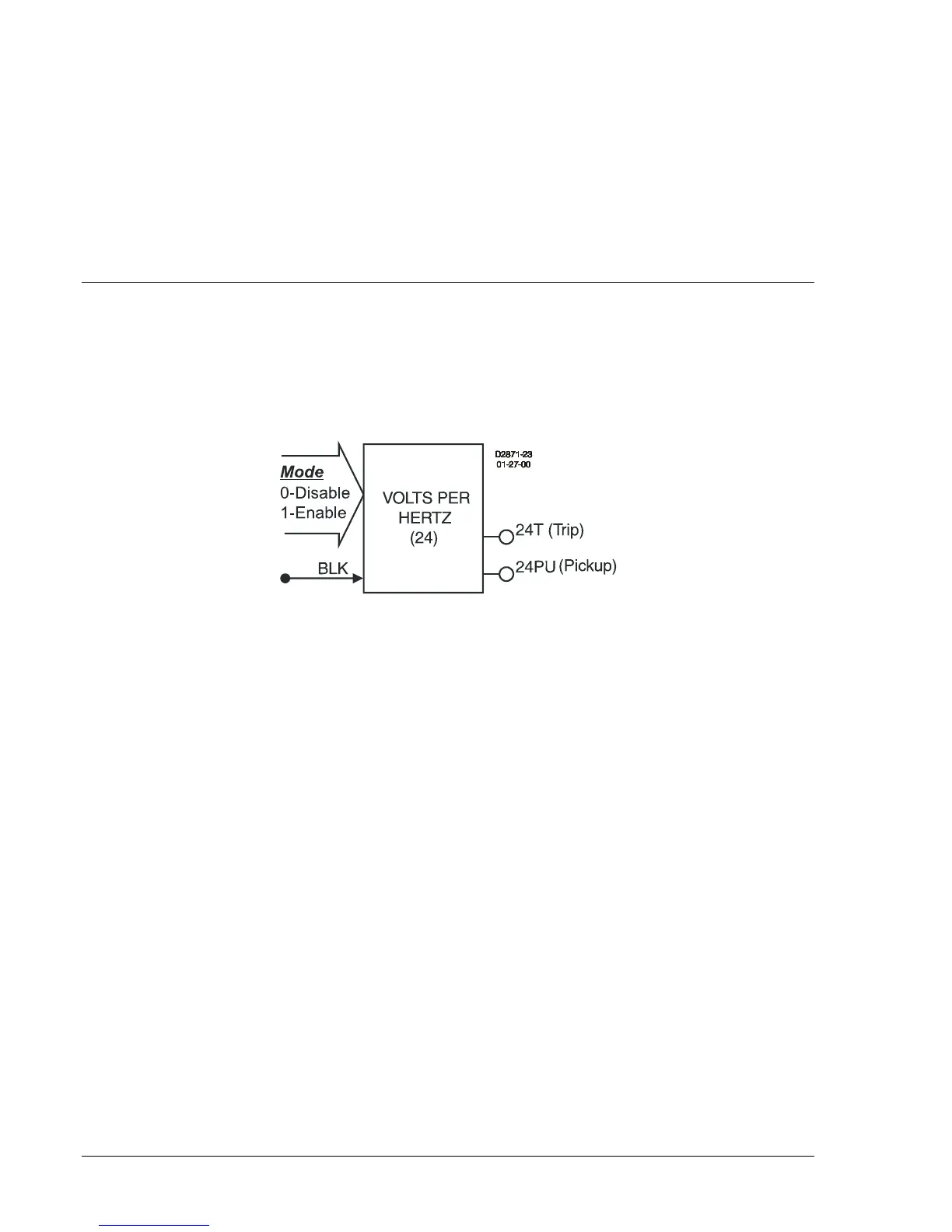
Figure 4-25 illustrates the inputs and outputs of the Volts per Hertz element. Element operation is
described in the following paragraphs.
Figure 4-25. Volts per Hertz Overexcitation Logic Block
The volts/hertz element has two outputs: 24T (trip) and 24PU (pickup). When monitored Volts per Hertz
increases above the pickup setting, the pickup output becomes TRUE and the element starts timing
toward a trip. The trip output becomes TRUE when the element timer times out.
The block (BLK) input is used to disable protection. A BESTlogic expression defines how the BLK input
functions. When this expression is TRUE, the element is disabled by forcing the outputs to logic 0 and
resetting the timer. This feature functions in a similar way to the torque control contact of an
electromechanical relay.
The 24 element is enabled or disabled by the Mode input. Two modes are available. Selecting Mode 0
disables protection. Mode 1 enables the 24 element.
The pickup setting determines the volts per hertz pickup level. The measured volts per hertz is always
calculated as the measured phase to phase voltage divided by the sensed system frequency and is
dependent upon VTP connection. When the measured volts per hertz rises above the pickup threshold,
the pickup element becomes TRUE and the integrating timer starts. If the volts per hertz remains above
the pickup threshold and the integration continues for the required time interval as defined by the
equations below and the set time dial, the trip output becomes TRUE.
If the target is enabled for the 24 element, the target reporting function will record a target when the trip
output is TRUE and the fault recording function trip logic expression is TRUE. See Section 6, Reporting
and Alarm Functions, Fault Reporting, for more information about target reporting.
The timer for the 24 element is an integrating timer with a variety of time dials and either an instantaneous
reset or a time delayed integrating reset. Equations 4-4 and 4-5 represent the trip time and reset time for
constant volts per hertz level.