9328900990 Rev L BE1-951 Protection and Control 4-19
menu labeled Settings. The Settings menu is used to select the setting group that the elements settings
apply to.
Using the pull-down menus and buttons, make the application appropriate settings to the Time
Overcurrent function. The 27R element is explained later in this section.
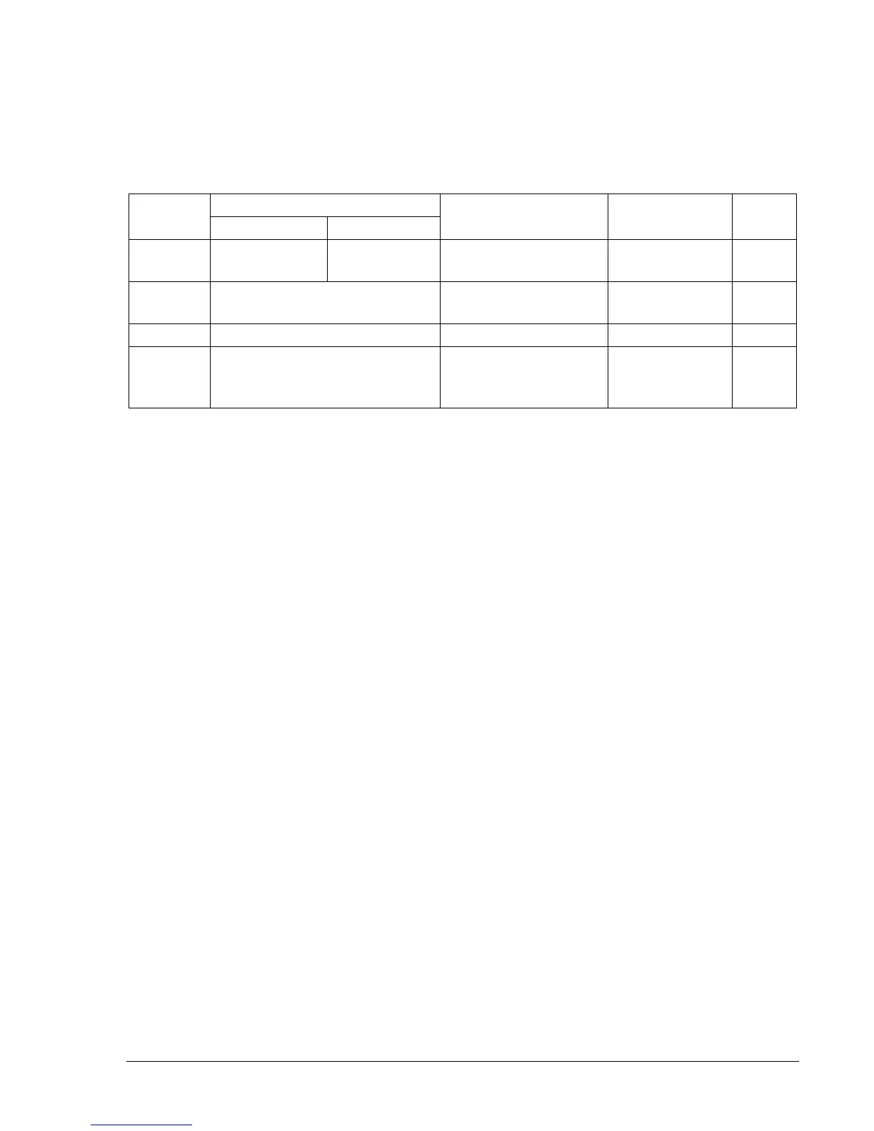
Table 4-7 summarizes the operating settings for Time Overcurrent.
Table 4-7. Operating Settings for Time Overcurrent
Range
Setting
1 A 5 A
Increment Unit of Measure Default
Pickup
0 = Disabled
0.1 to 3.2
0 = Disabled
0.5 to 16
0.02 for 0.1 to 9.99
0.1 for 10.0 to 16.0
Secondary Amps 0
Time Dial
0.0 to 9.9
0.0 to 99 (46 only)
0.1 N/A 0
Curve See Appendix A, Table A-1 N/A N/A V2
Direction
N = Nondirectional
F = Forward Directional
R = Reverse Directional
N/A N/A N
Example 1. Make the following changes to the 51P Time Overcurrent element in BESTCOMS. Refer
to
Figure 4-16.
Pickup: 10 secondary amps
Time Dial: 3.0
Curve: S1R
Directional Control: Forward
Voltage Restraint/Control for Time Overcurrent Protection
The 51P protection function can be set for voltage control or voltage restraint mode of operation (51V).
This feature is used to allow increased overcurrent sensitivity while providing security from operation due
to load current. This feature is also often used for generator backup protection to ensure delayed tripping
during a short circuit where the fault current contribution from the generator falls to a value close to the
full load rating of the generator.
When set for Control mode of operation, the phase overcurrent element is disabled until the measured
voltage drops below the threshold. Thus, as long as the voltage on the appropriate phase is above the
27R threshold setting, the overcurrent element will be blocked. When set for this mode of operation, the
51P pickup setting is typically set near or below load current levels.
When set for Restraint mode of operation, the pickup of the phase overcurrent element is adjusted based
upon the magnitude of the measured voltage.
Figure 4-17 shows how the overcurrent pickup threshold
setting is adjusted in response to the measured voltage level. Equation 4-1 determines the pickup level
for the 51P elements when the measured voltage is between 25% and 100% of the 27R threshold setting.
Below 25%, the pickup level stays at 25%. Above 100%, the pickup level stays at 100%. For example, if
the 27R threshold is set for 120V and the measured voltage on the appropriate phase is 100V, (83% of
the 27R threshold setting), the overcurrent pickup level for that phase will be reduced to 83% of its
setting. When set for this mode of operation, the 51P pickup setting is typically set above worst case, load
current levels.