9328900990 Rev L BE1-951 Testing and Maintenance 13-7
Step 1: Apply an external voltage source within the range of the voltages listed in Table 13-2 to contact
sensing inputs IN1, IN2, IN3, and IN4.
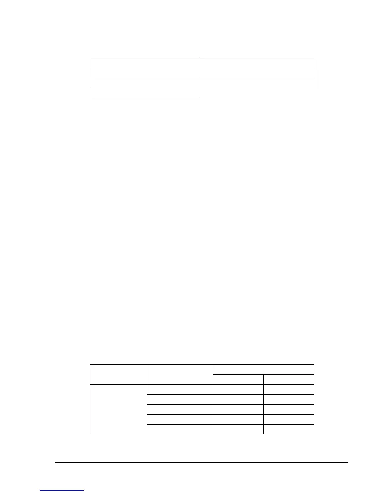
Table 13-2. Input Contact Wetting Voltage
Nominal Control Voltage Turn-On Range
48-125 Vac/dc 69 to 100 Vac or Vdc
125-250 Vac/dc 26 to 38 Vac or Vdc
24 Vdc 13 to 19 Vdc
Step 2: To verify that all inputs have been detected, transmit the command RG-STAT to retrieve INPUT
(1234) information. Input status can also be viewed at HMI Screen 1.4.1.
Control Outputs
Step 1: Transmit the commands ACCESS=, CS-OUT=ENA, CO-OUT=ENA, EXIT, and YES to enable
the output control override capability of the relay in order to pulse each output contact.
Step 2: From the HMI keypad, navigate to Screen 2.4.1, Output Control Override, to override control of
the outputs via the keypad.
Step 3: Once you have accessed the screen, press the Edit pushbutton to enable the override function.
(Step 1 enables logic override, pressing the Edit pushbutton enables selecting the control
action). Select an output to override by using the Left/Right arrow pushbuttons. Once selected,
use the Up/Down arrow pushbuttons to choose the type of action (P, 1, or 0) for the selected
output contact. Select the pulse (P) action for the alarm contact (A). Pressing the Edit
pushbutton again will force the alarm output contact action.
Step 4: Verify that the sequence of events recorder logged the events by sending the command RS-2 to
the relay (requesting the last two events it logged). The close-open pulse action should be listed
as two separate events.
Step 5: Repeat Step 3 for all desired output contacts and verify that the sequence of events recorder
logged the events.
Step 6: Transmit the commands CS-OUT=DIS, CO-OUT=DIS, EXIT, and YES to disable the output
control override capability of the relay.
Current Circuit Verification
Step 1: To verify IN and IQ, connect an ac current source to Terminals D1 and D2.
Step 2: Apply the appropriate current values in
Table 13-3 to the relay. Measured IN should correspond
to values in
Table 13-3 while IQ (negative-sequence current I2) should be 1/3 the applied value
±1.5% (For example, if the applied value equals 2 amps, IQ = 2/3 = 0.667 amps ±1.5% or ± .01
amps). Verify current measuring accuracy by transmitting the M command to the relay for each
applied current value. HMI Screen 3.7 also can be used to verify the IN and IQ current
measurement.
Table 13-3. Current Circuit Verification Values
Measured Current
Sensing Type Applied Current
Lower Limit Upper Limit
0.25 amps 0.2475 A 0.2525 A
1 amps 0.99 A 1.01 A
2 amps 1.98 A 2.02 A
3 amps 2.97 A 3.03 A
1 A
4 amps 3.96 A 4.04 A