4-68 BE1-951 Protection and Control 9328900990 Rev L
For single-phase sensing connections derived from a phase-to-phase source:
H1 Case: Terminals C14, C15, C16 (B, C, N) are connected in parallel. The single-phase
signal is connected between C13 (A) and the parallel group (AB, BC, and CA).
S1 Double-Ended Case: Terminals C15, C14, C13 (B, C, N) are connected in parallel. The single-phase
signal is connected between C16 (A) and the parallel group (AB, BC, and CA).
Also note that VM performs three of three testing for all connections. For 3W and 4W, phases A, B, and C
are actually tested. For single-phase connections, the terminals are connected in parallel as described
above and the single-phase is tested three times. This is implemented this way for convenience, allowing
the exact same code for both conditions.
Measuring slip frequency directly allows the function to rapidly determine if systems are in synchronism
and requires no timer or inherent delay (as compared to systems that check only that phase angle is held
within a window for some stretch of time). The moment parameters a), b), and c) in the previous
paragraph are met, the systems may be considered in synchronism and the output becomes TRUE.
Refer to Section 5, Metering, Frequency, for more information about slip frequency measurement.
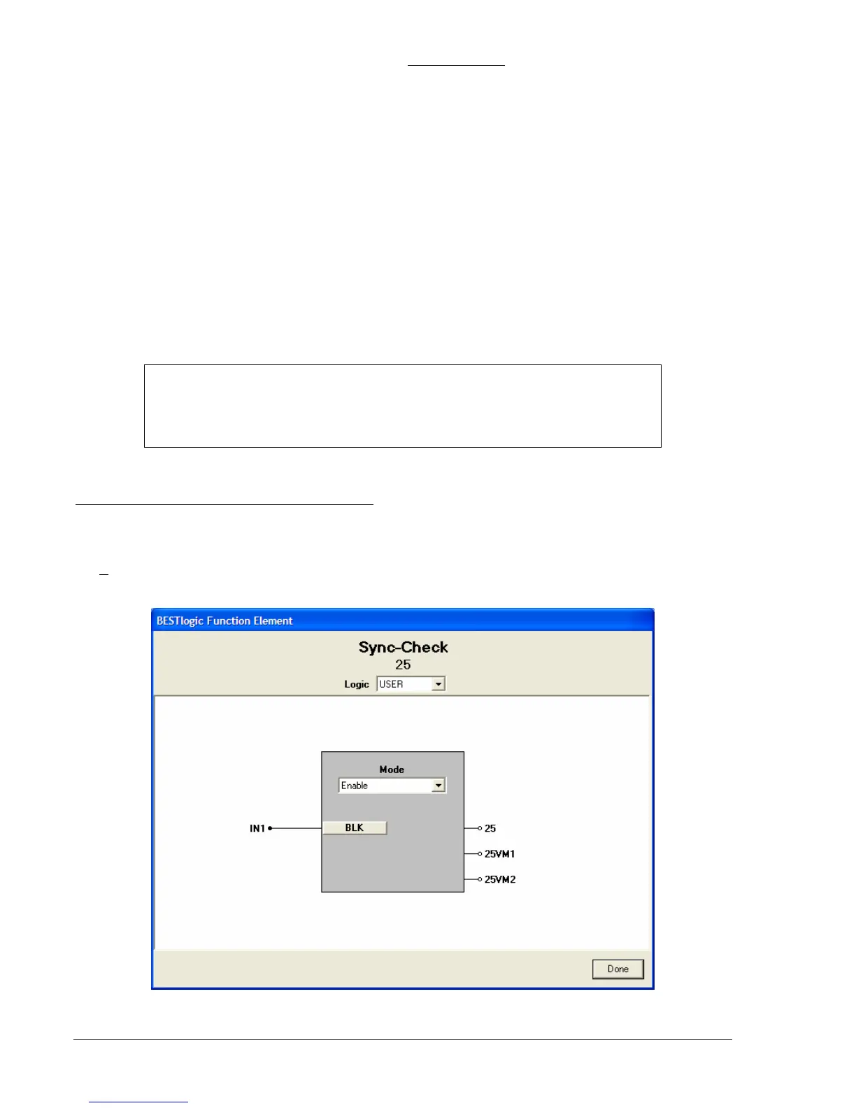
BESTlogic Settings for the Sync-Check Element
BESTlogic settings are made from the BESTlogic Function Element screen in BESTCOMS.
Figure 4-63
illustrates the BESTCOMS screen used to select BESTlogic settings for the Sync-Check element. To
open the BESTlogic Function Element screen for the Sync-Check element, select Voltage Protection from
the S
creens pull-down menu. Then select the BESTlogic button. Alternately, settings may be made using
SL-25 ASCII command.
Figure 4-63. BESTlogic Function Element Screen, 25
NOTE
If the 60FL element logic is TRUE and V block is enabled for phase blocking (P),
the 25 element will be blocked. For more information on the 60FL function, see
Voltage Transformer Fuse Loss Detection later in Section 4.