9328900990 Rev L BE1-951 Protection and Control 4-13
optional independent ground CT input (Mode G). More information about logic mode selection is provided
in the following BESTlogic Settings for Instantaneous Overcurrent subsection.
Each instantaneous overcurrent function has a pickup and time delay setting. When the measured current
increases above the pickup threshold, the pickup output (PU) becomes TRUE and the timer starts. If the
current stays above pickup for the duration of the time delay setting, the trip output (T) becomes TRUE. If
the current decreases below the dropout ratio, which is 95 percent, the timer is reset to zero.
The phase overcurrent protective functions include three independent comparators and timers, one for
each phase. If the current increases above the pickup setting for any one phase, the pickup output
asserts. If the trip condition is TRUE for any one phase, the trip logic output asserts.
If the target is enabled for the element, the target reporting function will record a target for the appropriate
phase when the protective function trip output is TRUE and the fault recording function trip logic
expression is TRUE. See Section 6, Reporting and Alarm Functions, Fault Reporting, for more
information about target reporting. The overcurrent elements have adaptable targets. If one is set for
directional control, it will report a 67 target (67A, B, C, N or G). If one is set for non-directional control it
will report a 50 target.
BESTlogic Settings for Instantaneous Overcurrent
BESTlogic settings are made from the BESTlogic Function Element screen in BESTCOMS.
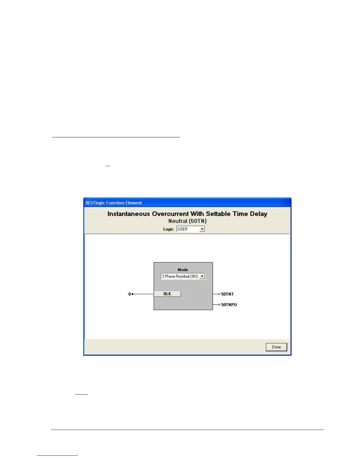
Figure 4-12
illustrates the BESTCOMS screen used to select BESTlogic settings for the 50T and 150T elements (the
Neutral 50TN element is shown). To open the BESTlogic Function Element screen, select Overcurrent
Protection from the S
creens pull-down menu. Then select the 50T or 150T tab. Open the BESTlogic
Function Element screen for the desired element by selecting the BESTlogic button corresponding with
the desired element. Alternately, these settings can be made using the SL-50T and SL-150T ASCII
commands.
Figure 4-12. BESTlogic Function Element Screen, Neutral (50TN)
At the top center of the BESTlogic Function Element screen is a pull-down menu labeled Logic. This
menu allows viewing of the BESTlogic settings for each preprogrammed logic scheme. A custom logic
scheme must
be created and selected in the Logic pull-down menu at the top of the screen before
BESTlogic settings can be changed. See Section 7, BESTlogic Programmable Logic.
Enable the 50T or 150T function by selecting its mode of operation from the Mode pull-down menu. To
connect the element's inputs, select the button for the corresponding input in the BESTlogic Function
Element screen. The BESTlogic Expression Builder screen will open. Select the expression type to be