9328900990 Rev L BE1-951 Protection and Control 4-59
Example 1. Make the following operating settings to the 62 element. Figure 4-52 illustrates these
settings.
Time Units: ms
T1 Time: 100
T2 Time: 0
Retrieving 62/162 Output Status Information from the Relay
The status of each logic variable can be determined from the ASCII command interface by using the RG-
STAT (report general-status) or the RL (report logic) commands. Status cannot be determined using
BESTCOMS. See Section 6, Reporting and Alarm Functions, General Status Reporting, for more
information.
RECLOSING
The BE1-951 reclosing function provides up to four reclosing attempts that can be initiated by a protective
trip or by one of the contact sensing inputs. The reclosers allow supervisory control and coordination of
tripping and reclosing with other system devices. Any of the four recloser shots can be used to select a
different setting group when the appropriate shot is reached in a reclosing sequence. This change in
setting groups allows changing protection coordination during the reclosing sequence. For example, you
could have a fast 51 curve on the first two trips in the reclosing sequence and then switch to a new group
on the second reclose that uses a slow 51 curve. Detailed information about relay setting groups can be
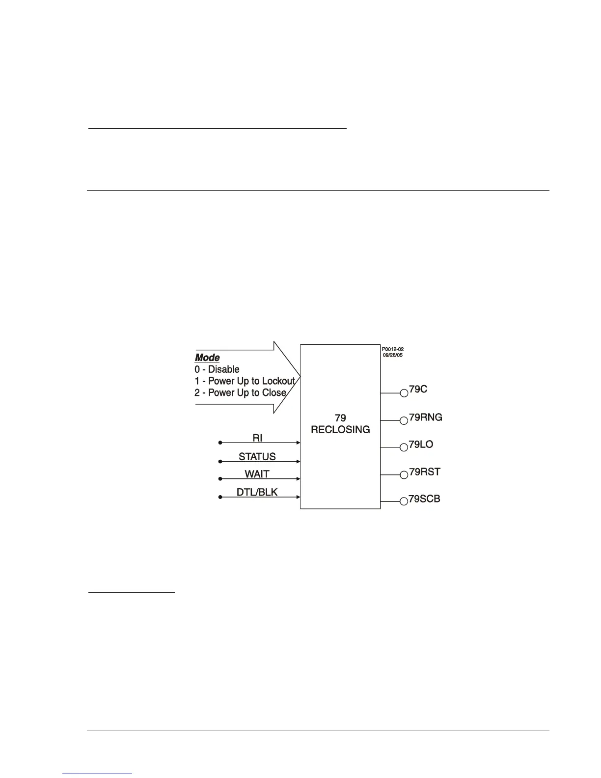
found earlier in this section under the heading of Setting Groups. Recloser function block inputs and
outputs are shown in
Figure 4-53 and are described in the following paragraphs. An overall logic diagram
for the recloser function is shown in
Figure 4-61.
Figure 4-53. Reclosing Logic Block
Inputs and Outputs
Reclose Initiate (RI)
The RI input is used with the 52 status input to start the reclose timers at each step of the reclosing
sequence. To start the automatic reclose timers, the RI input must be TRUE when the breaker status
input indicates that the breaker has tripped. To ensure that the RI input is recognized, a recognition
dropout timer holds the RI input TRUE for approximately 225 milliseconds after it goes to a FALSE state.
This situation might occur if the RI is driven by the trip output of a protective function. As soon as the
breaker opens, the protective function will drop out. The recognition dropout timer ensures that the RI
signal will be recognized as TRUE even if the breaker status input is slow in indicating breaker opening.
Figure 4-54 illustrates the recognition dropout logic and timing relationship.