4-44 BE1-951 Protection and Control 9328900990 Rev L
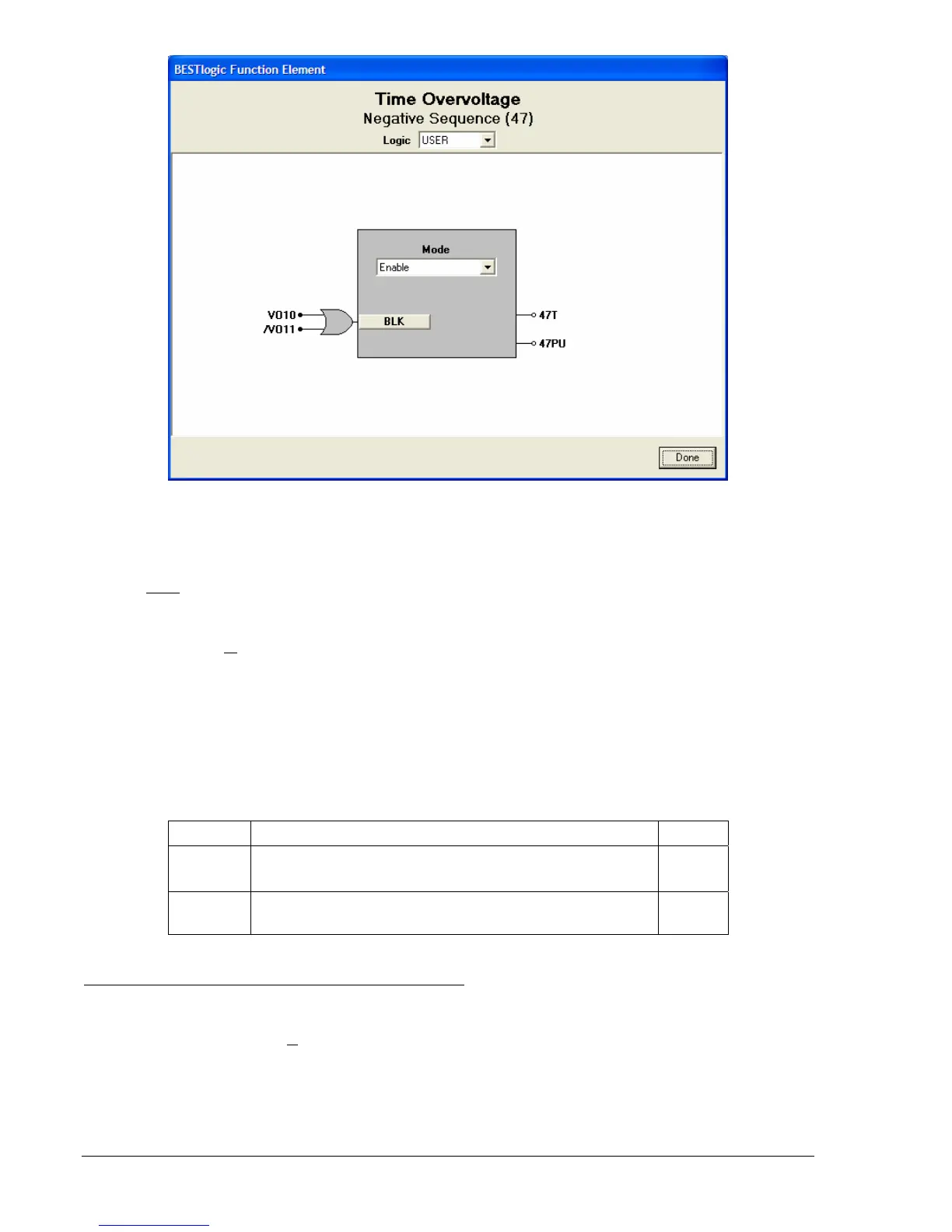
Figure 4-36. BESTlogic Function Element Screen, Negative Sequence (47)
At the top center of the BESTlogic Function Element screen is a pull-down menu labeled Logic. This
menu allows viewing of the BESTlogic settings for each preprogrammed logic scheme. A custom logic
scheme must
be created and selected in the Logic pull-down menu at the top of the screen before
BESTlogic settings can be changed. See Section 7, BESTlogic Programmable Logic.
Enable the Negative-Sequence Overvoltage with Settable Time Delay function by selecting its mode of
operation from the M
ode pull-down menu. To connect the elements inputs, select the button for the
corresponding input in the BESTlogic Function Element screen. The BESTlogic Expression Builder
screen will open. Select the expression type to be used. Then, select the BESTlogic variable, or series of
variables to be connected to the input. Select Save when finished to return to the BESTlogic Function
Element screen. For more details on the BESTlogic Expression Builder, see Section 7, BESTlogic
Programmable Logic. Select Done when the settings have been completely edited.
BESTlogic settings for Negative-Sequence Overvoltage are summarized in
Table 4-26.
Table 4-26. BESTlogic Settings for Negative-Sequence Overvoltage
Function Range/Purpose Default
Mode
0 = Disabled
1 = Enabled
0
BLK
Logic expression that disables function when TRUE. A
setting of 0 disables blocking.
0
Operating Settings for Negative-Sequence Overvoltage
Operating settings are made using BESTCOMS.
Figure 4-37 illustrates the BESTCOMS screen used to
select operational settings for the negative-sequence overvoltage element. To open the screen select
Voltage Protection from the S
creens pull-down menu and then select the 47 tab. Alternately, settings
maybe made using the S<g>-47 ASCII command or through the HMI interface using Screen 5.x.5.1
where x represents the number of the setting group.