EasyManuals Logo

Basler BE1-951 User Manual

Basler BE1-951
505 pages
To Next Page IconTo Next Page
To Previous Page IconTo Previous Page
Page #337 background imageLoading...
Page #337 background image
9328900990 Rev L BE1-951 Installation 12-17
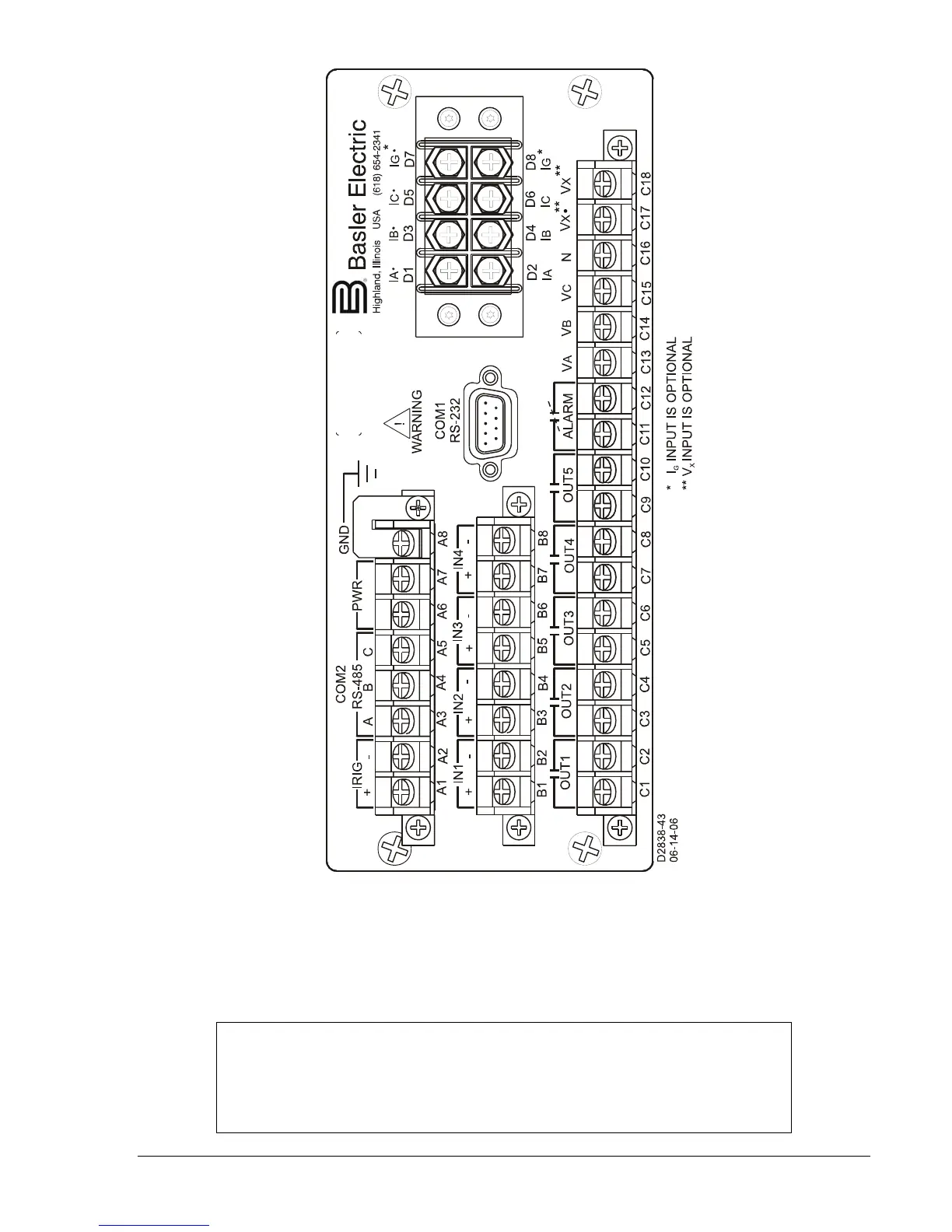
Figure 12-17. H1 Case Rear Panel Terminal Connections
Typical DC and AC Connections
Typical external DC and AC connections for the BE1-951 are shown in Figures 12-18 and 12-19.
NOTE
The relay should be hard-wired to earth ground with no smaller than 12 AWG
copper wire attached to the rear ground terminal of the relay case. When the
relay is configured in a system with other protective devices, a separate ground
bus lead is recommended for each relay.

Table of Contents

Questions and Answers:

Question and Answer IconNeed help?

Do you have a question about the Basler BE1-951 and is the answer not in the manual?

Basler BE1-951 Specifications

General IconGeneral
BrandBasler
ModelBE1-951
CategorySurge Protector
LanguageEnglish