6-22 BE1-951 Reporting and Alarm Functions 9328900990 Rev L
each function. Alternately, three different thresholds can be programmed to monitor one of the monitored
functions.
Breaker Alarms settings are made using BESTCOMS.
Figure 6-7 illustrates the BESTCOMS screen used
to select settings for the Breaker Alarms function. Alternately, settings may be made using the SB-BKR
ASCII command.
At the top of the screen is a pull-down menu labeled Logic. This menu allows viewing of the BESTlogic
settings for each preprogrammed logic scheme. A custom logic scheme must
be selected on this menu in
order to allow changes to be made to the mode and inputs of the function.
Using the pull-down menus and buttons, make the application appropriate settings to the Breaker Alarms
function.
Table 6-10 summarizes the SA-BKR command settings.
Table 6-10. SA-BKR Command Settings
Setting Range/Purpose Default
Mode
0 = Disabled
1 = Duty
2 = Operations
3 = Clearing Time
0
Point 1
Mode
0 to 100 in percent, increment = 0.01 0
Point 2
Mode
0 to 99,999 in operations, increment = 1 0
Threshold
Point 3
Mode
0, 20 to 1,000 in milliseconds (m), seconds (s), or cycles (c). Setting
is reported in milliseconds if less than 1 seconds.
0
TRIP CIRCUIT MONITOR
The trip circuit monitor continually monitors the circuit breaker trip circuit for
voltage and continuity. A closed breaker with no voltage detected across the trip
contacts can indicate that a trip circuit fuse is open or there is a loss of continuity
in the trip coil circuit. Breaker status (open or closed) is obtained through the
breaker status reporting function (configured by the SB-LOGIC command).
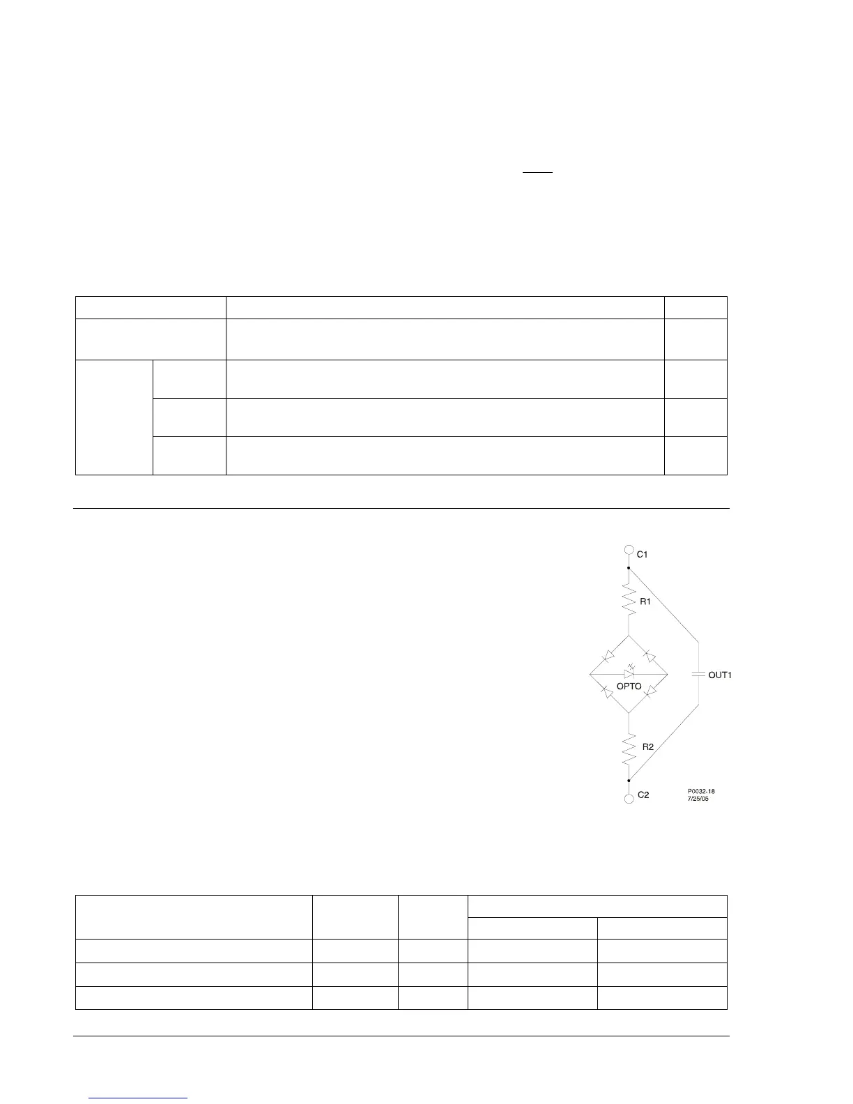
The detector circuit used by the trip circuit monitor is hardwired across the OUT1
contact. This contact is used in all of the preprogrammed logic schemes as the
main trip output. The detector circuit across OUT1 is not polarity sensitive
because the optical isolator used for detecting continuity is connected across a
full wave bridge. See Figure 6-9. The amount of current drawn through the
optical isolator circuit depends on the total input impedance for each power
supply voltage rating (see
Table 6-11). Figure 6-10 illustrates typical trip circuit
monitor connections for the BE1-951.
If the breaker status reporting function detects a closed breaker and no trip circuit
voltage is sensed by the trip circuit monitor after 500 milliseconds (coordination
delay time), an alarm bit in the programmable alarms function is set (OUT1 CKT
OPEN) and the OUT1MON BESTlogic variable is set to TRUE.
Table 6-11. Current Draw for each Power Supply Voltage Rating
Optical Isolator
Power Supply Voltage Rating R1 = R2 = R Total
Off (55% V) On (80% V)
24 Vdc
6.8 kΩ 14.6 kΩ
13.2 V (0.78 ma) 17.4 V (1.19 ma)
24/125 Vdc
18 kΩ 36 kΩ
26.4 V (0.68 ma) 38.4 V (1.02 ma)
125/250 Vdc
47 kΩ 94 kΩ
68.7 V (0.71 ma) 100 V (1.06 ma)
Figure 6-9. Trip
Detector Circuit