9328900990 Rev L BE1-951 Protection and Control 4-67
SYNCHRONISM-CHECK PROTECTION
25 - Synchronism-Check Protection
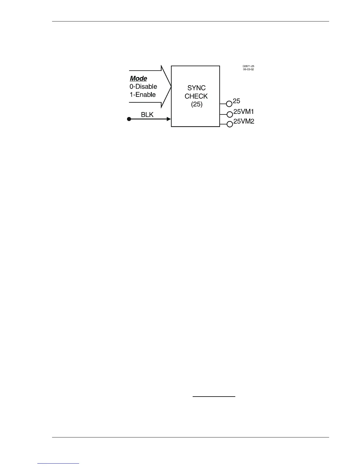
Figure 4-62 illustrates the inputs and outputs of the Sync-Check element. Element operation is described
in the following paragraphs.
Figure 4-62. Sync-Check Element
The Sync-Check element has three outputs: 25, 25VM1, and 25VM2. When monitored voltage between
the systems as measured by the phase VTs and the auxiliary Vx input circuits meets angle, voltage, and
slip criteria, the 25 output becomes TRUE. 25VM1 and 25VM2 are the voltage monitor outputs.
The Block (BLK) input is used to disable Sync-Checking. A BESTlogic expression defines how the BLK
input functions. When this expression is TRUE, the element is disabled by forcing the outputs to logic 0.
This feature functions in a similar way to the torque control contact of an electromechanical relay.
The 25 element is enabled or disabled by the Mode input. Two modes are available. Selecting Mode 0
disables the 25 element; Mode 1 enables the 25 element.
The 25 function module will change the 25 output to TRUE if the following conditions are met:
a) Phase angle between systems is less than setting.
b) Frequency error between systems is less than setting. As an additional parameter, the relay can
be set to only allow generator frequency greater than bus frequency, but the slip rate must be
greater than 0.010 Hz for sync to occur.
c) Voltage magnitude between systems is less than setting (the voltage used by the relay for this
feature is a voltage magnitude measurement, not a voltage phasor measurement).
The BE1-951 compares the VTP voltage magnitude and angle to the VTX voltage magnitude and angle
to determine synchronism. Therefore, proper connection of the VT inputs is vital to the correct operation
of the 25 function.
The relay automatically compensates for phase angle differences associated with the phase and auxiliary
VT connections, including single-phase VTP connections. That is, for a VTP selection of phase to phase
and a VTX selection of phase to neutral, the relay will automatically compensate for the 30-degree angle
between the two voltage sources. However, the relay does not scale for differences in magnitude
between the applied voltages. Delta V is a single-phase test only. For 3W VTP connection, the relay
compares V
AB
, to V
X
. For 4W VTP connection, it compares V
AN
to V
X
and for single-phase sensing the
relay compares the applied phase to V
X
. For example, if VTP = 4W (L-N) and VTX = AB (L-L), the angle
is automatically compensated for. However, one of the input magnitudes needs to be scaled by SQRT (3)
so that the magnitude of V
AN
on the phase must be equal V
AB
applied to the VX input is equivalent under
sync conditions. Note: The sync-check will not work if VTX connections are set for residual voltage input
VTX = RG.
For clarification on single-phase VTP connections, refer to the interconnection diagrams shown in Section
12, Installation, of this manual. The single-phase parallel connections ensure that the zero-crossing circuit
is always connected to the sensed circuit.
For single-phase sensing connections derived from a phase-to-neutral
source:
H1 Case: Terminals C13, C14, C15 (A, B, C) are connected in parallel. The single-phase
signal is connected between the parallel group and C16 (N).
S1 Double-Ended Case: Terminals C16, C15, C14 (A, B, C) are connected in parallel. The single-phase
signal is connected between the parallel group and C13 (N).