9328900990 Rev L BE1-951 BESTlogic Programmable Logic 7-9
Copying and Renaming Preprogrammed Logic Schemes
Copying a preprogrammed logic scheme to the active logic (Logic Name) and assigning a unique name is
accomplished by selecting the desired logic scheme in BESTCOMS and then typing over the logic
scheme's name. Changes are not activated until the new settings have been uploaded to the device.
Creating or Customizing a Logic Scheme
Before customizing a preprogrammed logic scheme, the scheme must be renamed. The following
procedure outlines the process of customizing or creating a logic scheme:
Step 1. Copy the preprogrammed scheme.
Step 2. Rename the scheme with a unique, non-preprogrammed, name.
Step 3. Using BESTCOMS, enable or disable the desired relay functions.
Step 4. Edit the logic expressions, as required.
Step 5. Save the changes. Refer to Section 14, BESTCOMS Software, for more information on
how to save and export settings files.
Sending and Retrieving Relay Settings
Retrieving Relay Settings
To retrieve settings from the relay, the relay must be connected to a computer through a serial port. Once
the necessary connections are made, settings can be downloaded from the relay by selecting Download
Settings from Device on the Communication pull-down menu.
Sending Relay Settings
To send settings to the relay, the relay must be connected to a computer through a serial port. Once the
necessary connections are made, settings can be uploaded to the relay by selecting Upload Settings to
Device on the C
ommunication pull-down menu.
Debugging the Logic Scheme
If there are problems with a customized logic scheme, the RG-STAT command can be used to check the
status of all logic variables. More information about the RG-STAT command can be found in Section 6,
Reporting and Alarm Functions.
USER INPUT AND OUTPUT LOGIC VARIABLE NAMES
Assigning meaningful names to the inputs and outputs makes sequential events reports easier to
analyze. Input and output logic variable names are assigned by typing them into the appropriate text box
on the related BESTCOMS screen. All of the BE1-951’s inputs, outputs, and 43 switches have labels that
can be edited.
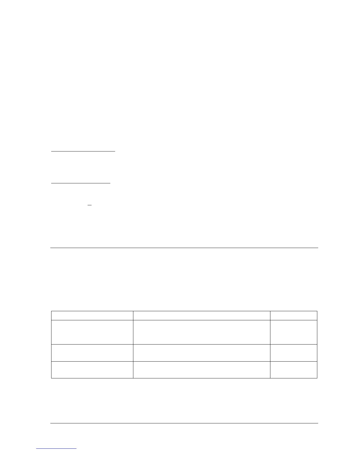
Table 7-2 shows the range and purpose of each label. Alternately, labels may be edited
using the SN ASCII command.
Table 7-2. Programmable Variable Name Setting
Settings Range/Purpose Default
Name/Label
1 to 10 characters.
User name to replace <var> in the RS report.
INPUT_x
SWITCH_x43
VOx_LABEL
True/Energized State
1 to 7 characters.
Used to replace default labels.
TRUE
False/De-Energized State
1 to 7 characters.
Used to replace default labels.
FALSE