13-44 BE1-951 Testing and Maintenance 9328900990 Rev L
Step 6: (Optional.) Repeat Steps 2 through 5 for the B-phase and C-phase voltage inputs.
Step 7: (Optional.) Repeat Steps 2 through 6 for Setting Groups 1, 2, and 3.
Over/Underfrequency (81)
Purpose: To verify the operating accuracy of the 81/181/281/381/481/581 protection elements.
Reference Commands: SL-x81, SL-VO
Pickup Verification
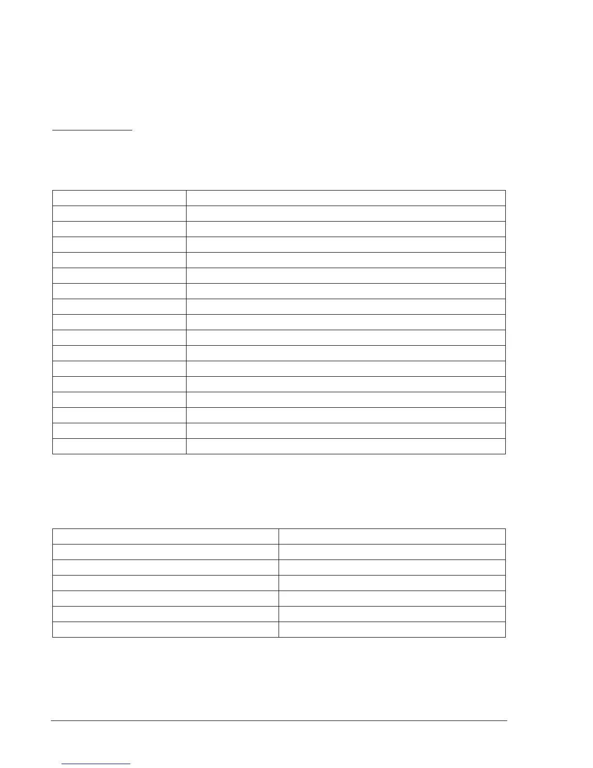
Step 1: Prepare the x81 pickup functions for pickup testing by transmitting the commands in
Table
13-64 to the relay.
Table 13-64. x81 Pickup Test Commands
Command Purpose
A= Gains write access.
SL-N=NONE Zero out custom logic settings. Overwrite with LOGIC=NONE settings.
Y Confirm overwrite.
SL-N=FREQTEST Sets FREQTEST as custom logic name.
SL-81=1,0 Enables 81, disables blocking.
SL-181=1,0 Enables 181, disables blocking.
SL-281=1,0 Enables 281, disables blocking.
SL-381=1,0 Enables 381, disables blocking.
SL-481=1,0 Enables 481, disables blocking.
SL-581=1,0 Enables 581, disables blocking.
SL-VO1=81T+581T Enables OUT1 to close for 81 or 581 trip.
SL-VO2=181T Enables OUT2 to close for 181 trip.
SL-VO3=281T Enables OUT3 to close for 281 trip.
SL-VO4=381T Enables OUT4 to close for 381 trip.
SL-VO5=481T Enables OUT5 to close for 481 trip.
EXIT;Y Exit and save settings.
Step 2: Transmit the commands in
Table 13-65 to the relay. These commands set the pickup value and
operating mode (underfrequency or overfrequency) for each of the x81 functions.
Table 13-65. x81 Pickup and Mode Settings
Pickup and Mode Settings Purpose
S0-81=42,0,U Sets 81 PU at 42 Hz, Underfrequency.
S0-181=46,0,U Sets 181 PU at 46 Hz, Underfrequency.
S0-281=48,0,U Sets 281 PU at 48 Hz, Underfrequency.
S0-381=65,0,O Sets 381 PU at 65 Hz, Overfrequency.
S0-481=67,0,O Sets 481 PU at 67 Hz, Overfrequency.
S0-581=69,0,O Sets 581 PU at 69 Hz, Overfrequency.
Step 3: Prepare to monitor x81 function operation. Operation can be verified by monitoring the
programmed output contacts or HMI Screen 1.5.2.
Step 4: Connect and apply a 120 Vac, 60-hertz voltage source to Terminals C13 (A-phase) and C16
(Neutral).