4-48 BE1-951 Protection and Control 9328900990 Rev L
Example 1. Make the following BESTlogic settings to the 81 element. Refer to Figure 4-39.
Mode: Phase VT Input
BLK: 0
Operating Settings for Over/Under Frequency
Operating settings for the 81 elements consist of pickup values, time delay values, and a mode setting
that defines whether an element provides underfrequency or overfrequency protection. The pickup value
determines the value of frequency required for the element to start timing toward a trip. The time delay
value determines the length of time between reaching the pickup value and tripping. Time delays can be
set in milliseconds, seconds, or cycles. The default is milliseconds if no unit of measure is specified.
Minimum timing resolution is two cycles. A time delay setting of zero makes the element instantaneous
with no intentional time delay.
Operating settings are made using BESTCOMS.
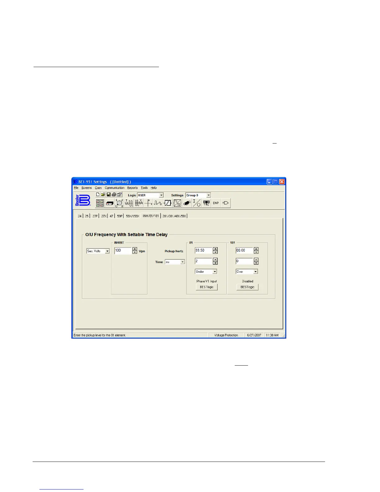
Figure 4-40 illustrates the BESTCOMS tab used to
select operational settings for the six Over/Underfrequency elements. To open the BESTlogic Function
Element screen for Over/Underfrequency element, select Voltage Protection from the S
creens pull-down
menu and select the INH/81/181 or 281/381/481/581 tab. Alternately, settings may be made using the
S<g>-<x>81 ASCII command or the HMI interface using Screens 5.x.12.1 through 5.x.12.6 where x
equals the setting group number.
Figure 4-40. Voltage Protection Screen, INH/81/181 Tab
At the top of the screen is a pull-down menu labeled Logic. This menu allows viewing of the BESTlogic
settings for each preprogrammed logic scheme. A custom logic scheme must
be created and selected in
the Logic pull-down menu at the top of the screen before BESTlogic settings can be changed. See
Section 7, BESTlogic Programmable Logic. To the right of the Logic pull-down menu is a pull-down menu
labeled Settings. The Settings menu is used to select the setting group that the elements settings apply
to.
Using the pull-down menus and buttons, make the application appropriate settings to the
over/underfrequency element.
Frequency protection can be inhibited when the monitored voltage decreases below a user-defined level.
The undervoltage inhibit level is set using the S<g>-81INH command or Screen 5.x.12.7 of the front panel
HMI.
The voltage inhibit setting unit of measure depends upon the VTP and VTX connection settings. For 4-
wire or PN connections it is secondary VPN. For 3-wire or PP connections it is secondary VPP.