9328900990 Rev L BE1-951 Protection and Control 4-21
The default unit of measure for the Pickup Threshold setting is secondary amps. Secondary amps (Sec
Amps), per unit amps (Per U Amps), and percent amps (% Amps) can also be selected as the pickup
setting unit of measure.
At the top center of the screen is a pull-down menu labeled Logic. This menu allows viewing of the
BESTlogic settings for each preprogrammed logic scheme. A custom logic scheme must
be created and
selected in the Logic pull-down menu at the top of the screen before BESTlogic settings can be changed.
See Section 7, BESTlogic Programmable Logic. To the right of the Logic pull-down menu is a pull-down
menu labeled Settings. The Settings menu is used to select the setting group that the elements settings
apply to.
Using the pull-down menus and buttons, make the application appropriate settings to the Voltage
Restraint element.
Table 4-9 summarizes the function’s modes of operation.
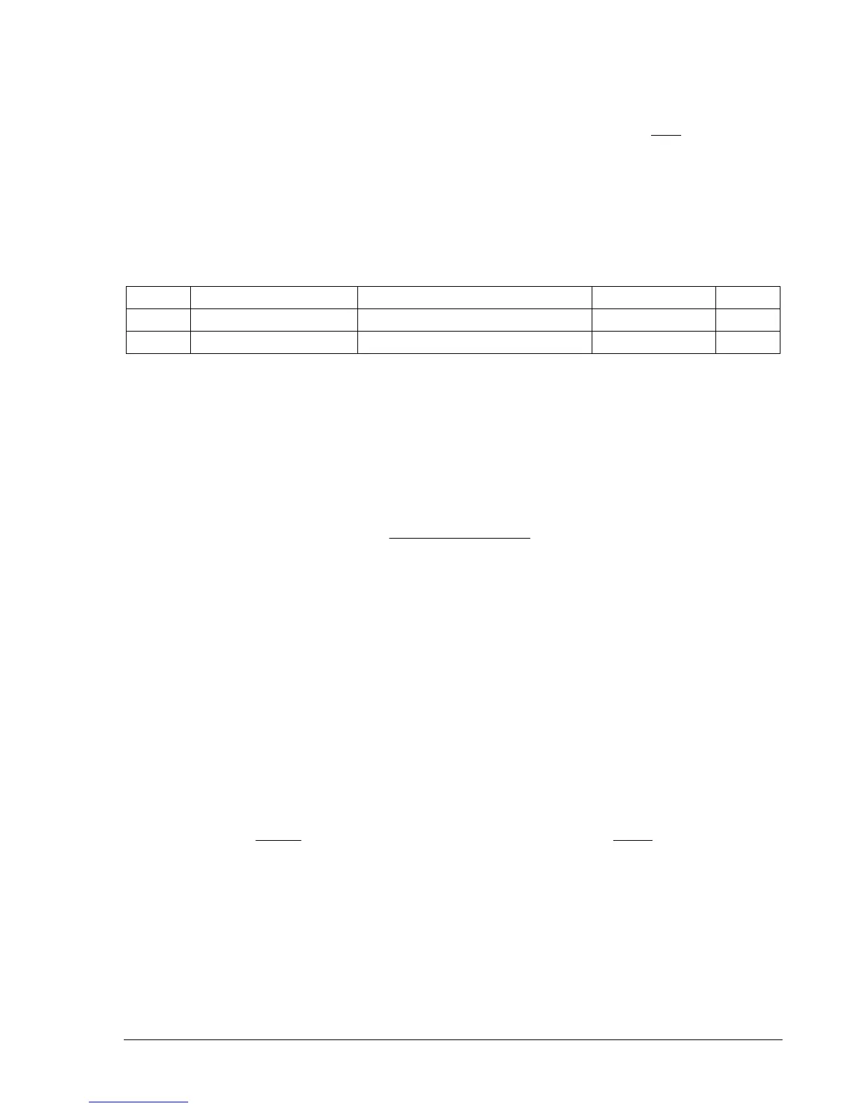
Table 4-9. Operating Settings for Voltage Restraint/Control for Time Overcurrent
Setting Range Increment Unit of Measure Default
Pickup 30 to 250, 0 = Disable 0.1 for 30 to 99, 1.0 for 100 to 250 Volts 0
Mode C (control), R (restraint) N/A N/A R
Pickup Threshold. A setting of zero disables voltage restraint/control and allows the 51P time overcurrent
function to operate normally. When voltage restraint or control is desired, the pickup value can be set
over a range of 30 to 250 volts. Setting curve coefficients is discussed later in this section.
Mode Setting (Mode). Two mode settings are available: Restraint and Control.
Restraint I. In Restraint mode, the 51P pickup level is reduced linearly when the sensing voltage
decreases below the restraint pickup level. The 51P pickup level is determined by Equation 4-1.
settingpickup51P
settingpickuprestraint
levelvoltagesensing
LevelPickupActual ×=
Equation 4-1. Restraint Pickup Level
Control I. In Control Mode, pickup level is as selected by the 27R pickup setting.
Control or restraint operation can also be set by the S<g>-27R command.
Programmable Curves
Time current characteristics for trip and reset programmable curves are defined by Equation 4-2 and
Equation 4-3 respectively. These equations comply with IEEE standard C37.112-1996. The curve specific
coefficients are defined for the standard curves as listed in Appendix A, Time Overcurrent Characteristic
Curves. When time current characteristic curve P is selected, the coefficients used in the equation are
those defined by the user. Definitions for these equations are provided in
Table 4-10.
Equation 4-2. Time OC Characteristics for Trip
KBD
CM
AD
T
N
T
++
−
=
Equation 4-3. Time OC Characteristics for Reset
1
2
−
=
M
RD
T
R