13-8 BE1-951 Testing and Maintenance 9328900990 Rev L
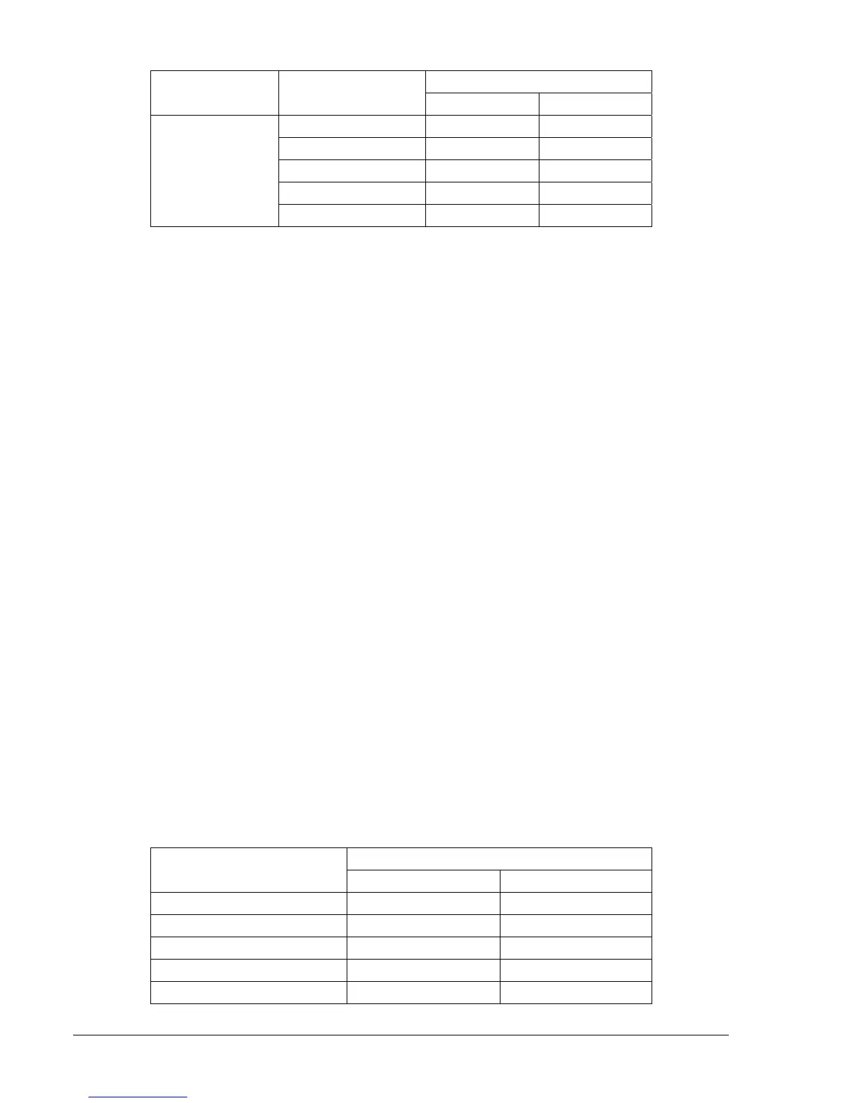
Table 13-3. Current Circuit Verification Values (continued)
Measured Current
Sensing Type Applied Current
Lower Limit Upper Limit
1 amps 0.99 A 1.01 A
5 amps 4.95 A 5.05 A
10 amps 9.90 A 10.10 A
15 amps 14.85 A 15.15 A
5 A
20 amps 19.80 A 20.20 A
Step 3: To verify IP and IG, connect a suitably sized jumper wire across relay terminals D2 and D3, D4
and D5, and D6 and D7. Apply an ac current source to Terminals D1 and D8.
Step 4: Apply the appropriate current values in
Table 13-3 to the relay. Verify current measuring
accuracy by transmitting the M command to the relay for each applied current value. HMI
Screens 3.5 and 3.6 also can be used to verify current measurements. Screen 3.7, IN, will read
3 times the phase value.
Step 5: Leave current circuit connected and de-energized. These test connections will be used later
when verifying power readings.
Three-Phase Voltage Circuit Verification
Step 1: Connect an ac voltage source at nominal frequency between relay Terminals C13 (A-phase)
and C16 (Neutral terminal). Apply 100 volts and verify voltage-measuring accuracy by
transmitting the M command to the relay. Readings should be: M-VA = 100 volts, M-VAB = 100
volts, M-VCA = 100 volts, M-3V0 = 100 volts and M-V2 = 33.4 volts (applied divided by 3), all at
±1.0%. HMI Screens 3.1, 3.2, and 3.4 can also be monitored to verify voltage measurements.
Step 2: Connect an ac voltage source at nominal frequency between relay Terminals C14 (B-phase)
and C16 (Neutral Terminal). Apply 100 volts and verify voltage-measuring accuracy by
transmitting the M command to the relay. Readings should be: M-VB = 100 volts, M-VAB = 100
volts, M-VBC = 100 volts, M-3V0 = 100 volts and M-V2 = 33.4 volts (applied divided by 3), all at
±1.0%. HMI Screens 3.1, 3.2, and 3.4 can also be monitored to verify voltage measurements.
Step 3: Connect an ac voltage source at nominal frequency between relay Terminals C15 (C-phase)
and C16 (Neutral Terminal). Apply 100 volts and verify voltage-measuring accuracy by
transmitting the M command to the relay. Readings should be: M-VC = 100 volts, M-VBC = 100
volts, M-VCA = 100 volts, M-3V0 = 100 volts and M-V2 = 33.4 volts (applied divided by 3), all at
±1.0%. HMI Screens 3.1, 3.2, and 3.4 can also be monitored to verify voltage measurements.
Step 4: Connect relay Terminals C13 (A-phase), C14 (B-phase), and C15 (C-phase) together. Connect
an ac voltage source at nominal frequency to the three jumpered terminals and the Neutral
Terminal (C16).
Step 5: Apply the voltage values listed in
Table 13-4 and verify voltage measuring accuracy by
transmitting the M command to the relay. HMI Screen 3.1 can also be monitored to verify
voltage measurements.
Table 13-4. Voltage Circuit Verification Values
Measured Voltage
Applied Voltage
Lower Limit Upper Limit
80 volts 79.2 V 80.8 V
100 volts 99.0 V 101.0 V
120 volts 118.8 V 121.2 V
140 volts 138.6 V 141.4 V
160 volts 156.8 V 163.2 V